Installation
Technical Catalogue
6
45
TCGB0051 rev 0 - 09/2009
6.7.3. Caution on use of CSC-5S
Follow strictly instructions of CSC-5S Installation Manual. This control requires power supply ~1 220-240 V.
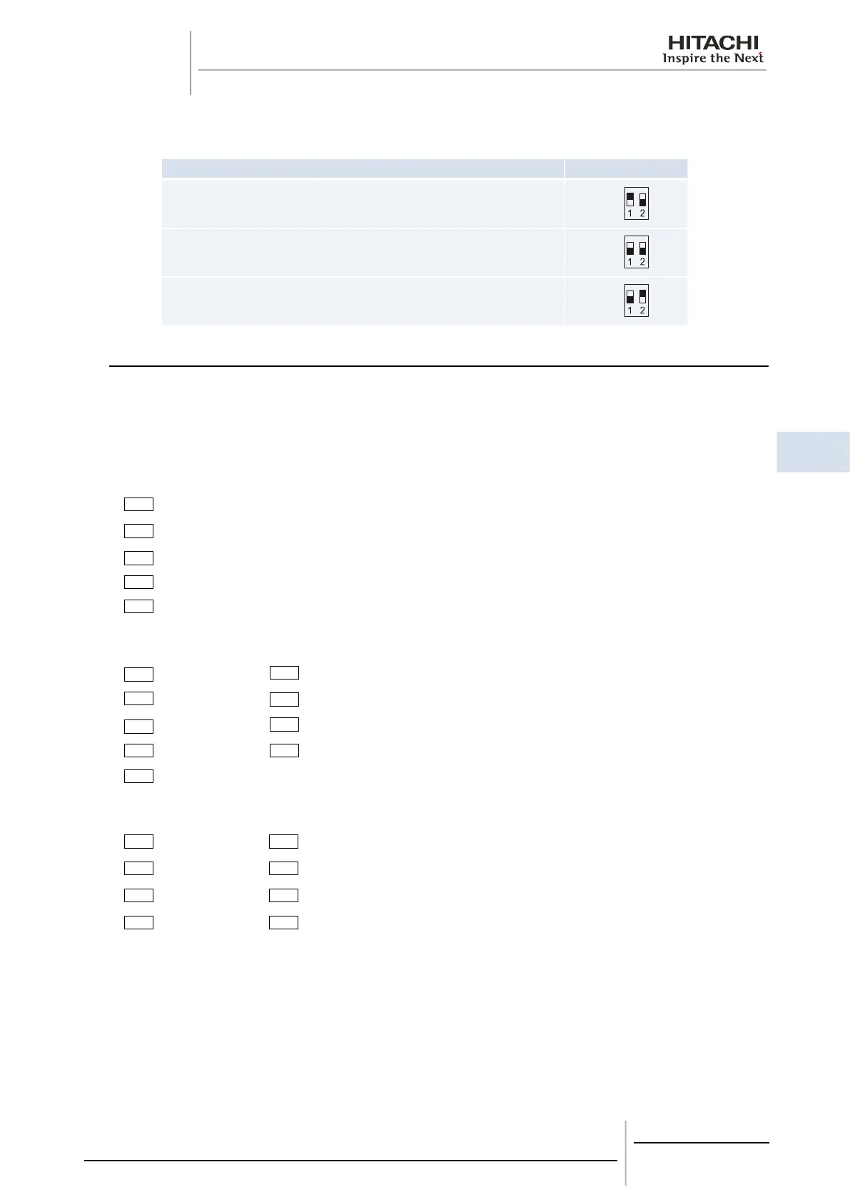
6.7.4. Transmitting setting (on chiller control PCB)
Operation DSW
Before shipment, No. 1 pin of DSW10 is set at ON side
In case that Chiller Unit quantity in the same H-Link is 2 or more, set No. 1 pin of
DSW10 at the OFF side from 2
nd
Unit. If only one Chiller Unit is used, no setting is
required.
In case of applying high voltage to the terminal TB1 (E,F), the fuse on the PCB is cut.
In such a case, rst connect the wiring to TB1 (E,F) and then turn “ON” DSW-2
6.8. Installation nal check
Inspect the installation work according to all documents and drawings. Sub-chapter 6.8.1 shows the minimum check
points.
6.8.1. Installation work check list
1. Is the unit solidly mounted and levelled?
2. Is the installation location adequate?
Indoor Installation
Space for Maintenance Work
Noise and Vibration
Sunshine and other Heat Sources
Appearance
3. Is the water piping system adequate?
Tube Size Water Drain
Length Water Control
Flexible Joint Air Purge
Insulation Pressure Control
Strainer
4. Is the electrical wiring system adequate?
Wire Size Tightened Connections
Switch Size Operation Control Devices
Fuse Size Safety Devices
Voltage and Hz Interlock
5. Have the R, S and T phases of the water Chiller correctly been connected to the R, S and T phases of the main
power source?
6. Are the stop valves for the condenser liquid line open?
7. Have the packing glands and the cap nuts for the stop valves been tightened?
8. Is BMS connected correctly and operate as decided?
 Loading...