BF15DmBF20D
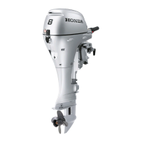
1)
Using a
45"
cutter, remove enough material
to
produce
a smooth and concentric seat. Turn the cutter clockwise,
never counterclockwise. Continue
to
turn the cutter as
you lift it from the valve seat.
2) Use the 32" and
60"
cutter
to
narrow and adjust the
valve seat
so
that it contacts the middle of the valve
face.
The 32" cutter removes material from the top edge.
The
60"
cutter removes material from the bottom
edge.
3) Be sure that the width of the finished valve seat is within
specification.
I
Standard
valve
I
0.9
-
1.1
mm (0.035
-
0.043
in)
I
seat width
4)
Make a light pass with
45"
cutter
to
remove any possible
burrs at the edges of the seat.
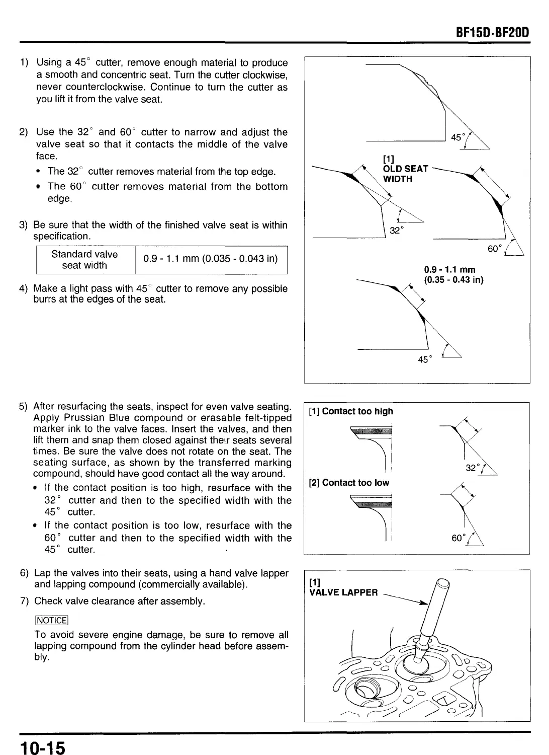
5)
After resurfacing the seats, inspect for even valve seating.
Apply Prussian Blue compound or erasable felt-tipped
marker ink
to
the valve faces. Insert the valves, and then
lift them and snap them closed against their seats several
times. Be sure the valve does not rotate on the seat. The
seating surface, as shown by the transferred marking
compound, should have good contact all the way around.
If the contact position is
too
high, resurface with the
32" cutter and then
to
the specified width with the
45"
cutter.
If the contact position is
too
low, resurface with the
60"
cutter and then to the specified width with the
45"
cutter.
6)
Lap the valves into their seats, using a hand valve lapper
7)
Check valve clearance after assembly.
and lapping compound (commercially available).
-1
To avoid severe engine damage, be sure to remove
all
lapping compound from the cylinder head before assem-
bly.
-----?A
60'
\
32"
0.9
-
1.1
mm
-A
45"
I
[l]
Contact too
high
[2]
Contact
too
low
1
10-1
5
 Loading...