B
F15
D.
BF20
D
2.
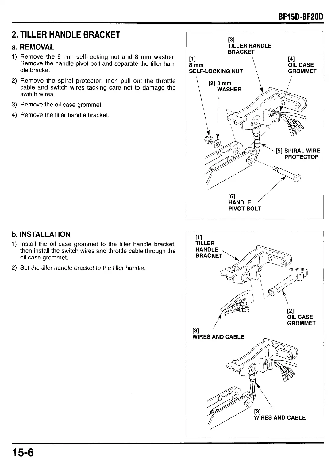
TILLER HANDLE BRACKET
a.
REMOVAL
1)
Remove the
8
mm self-locking nut and
8
mm washer.
Remove the handle pivot bolt and separate the tiller han-
dle bracket.
2)
Remove the spiral protector, then pull out the throttle
cable and switch wires tacking care not
to
damage the
switch wires.
3)
Remove the
oil
case grommet.
4)
Remove the tiller handle bracket.
b.
INSTALLATION
1)
Install the oil case grommet to the tiller handle bracket,
then install the switch wires and throttle cable through the
oil case grommet.
2)
Set the tiller handle bracket
to
the tiller handle.
11
1
8
mm
[31
TILLER HANDLE
BRACKET
\
141
OIL CASE
SELF-LOCKING NUT GROMMET
\
PI
8
mm
PROTECTOR
HANDLE
PIVOT BOLT
GROMMET
15-6

 Loading...