BF15DmBF20D
b.
INSPECTION
THERMOSTAT
1)
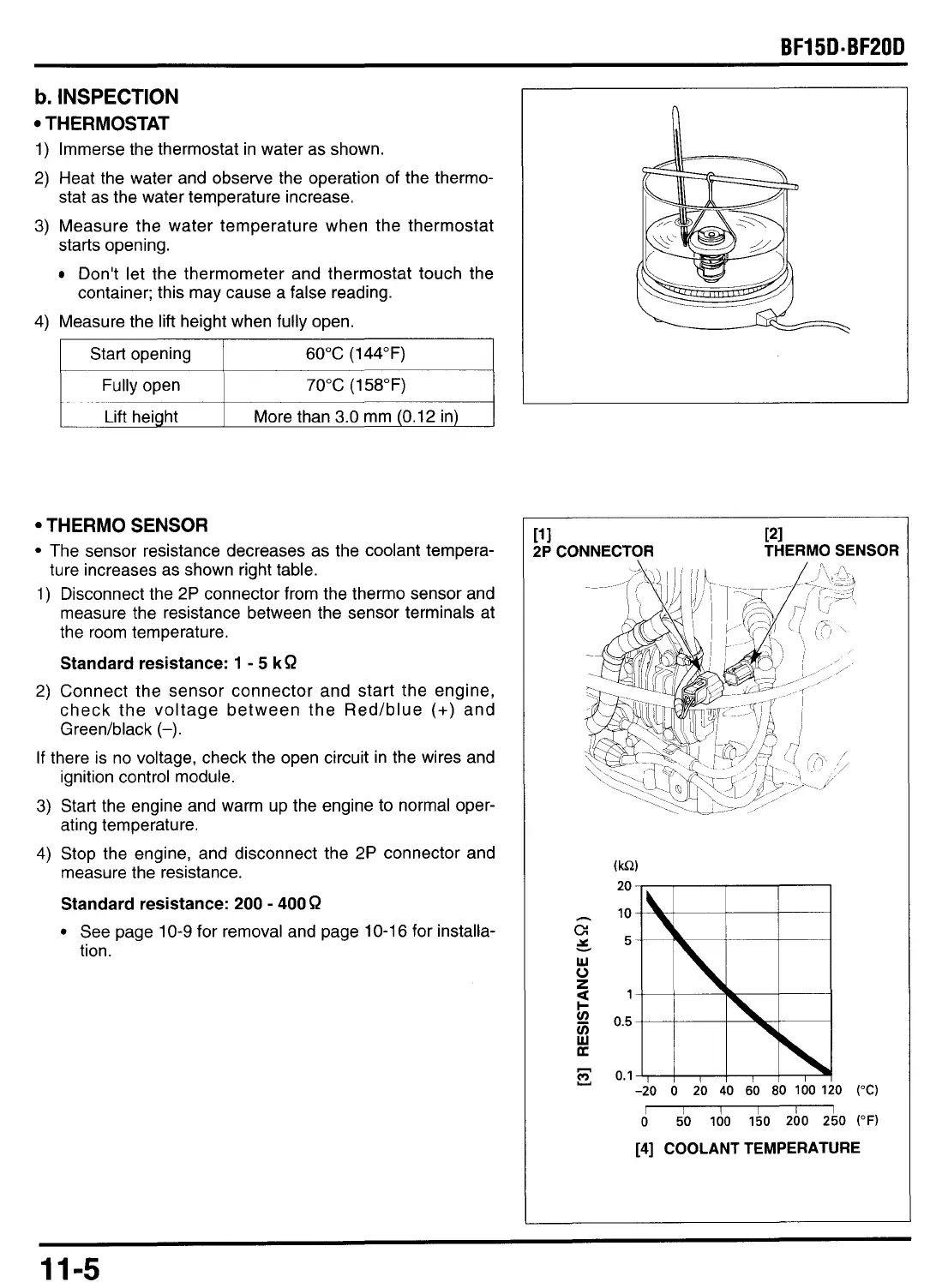
Immerse the thermostat in water as shown.
2)
Heat the water and observe the operation of the thermo-
stat as the water temperature increase.
3)
Measure the water temperature when the thermostat
starts opening.
Don't let the thermometer and thermostat touch the
container; this may cause a false reading.
4)
Measure the lift height when fully open.
THERMO SENSOR
The sensor resistance decreases as the coolant tempera-
1)
Disconnect the
2P
connector from the thermo sensor and
measure the resistance between the sensor terminals at
the room temperature.
Standard resistance: 1
-
5
kR
2)
Connect the sensor connector and start the engine,
check the voltage between the Red/blue
(+)
and
Greedblack
(-).
If
there is no voltage, check the open circuit in the wires and
ignition control module.
3)
Start the engine and warm up the engine
to
normal oper-
ating temperature.
4)
Stop the engine, and disconnect the
2P
connector and
measure the resistance.
Standard resistance: 200
-
400
R
See page
10-9
for removal and page
10-16
for installa-
tion.
ture increases as shown right table.
PI
THERMO SENSOR
11
1
2P
CONNECTOR
20
10
5
1
0.5
0.1
-20
0
20
40
60
80
100
1
1
0
510
Id0 150
200 250
(OF)
I
[4]
COOLANT TEMPERATURE
11-5

 Loading...