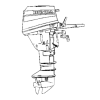
BF15D-BF20D
2.
FRICTION
ADJUSTING
LEVER
a.
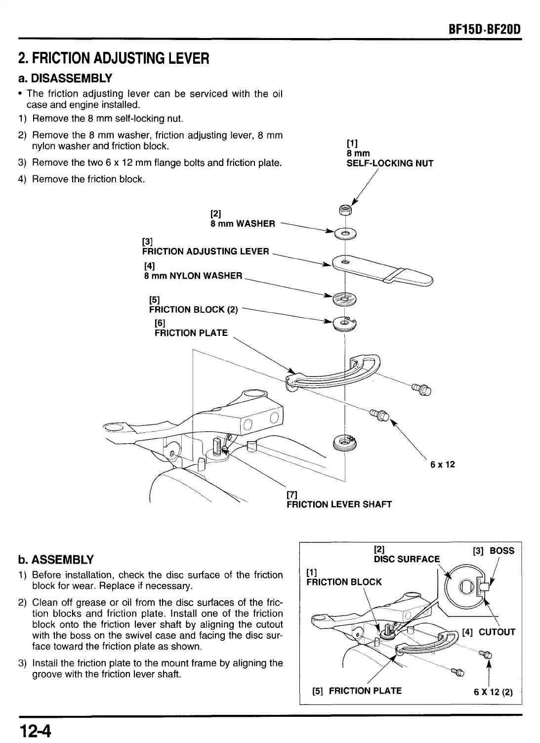
DISASSEMBLY
The friction adjusting lever can be serviced with the oil
1) Remove the
8
mm self-locking nut.
2) Remove the
8
mm washer, friction adjusting lever,
8
mm
nylon washer and friction block.
3)
Remove the two
6
x
12 mm flange bolts and friction plate.
case and engine installed.
111
8
mm
SELF-LOCKING NUT
4)
Remove the friction block.
121
8
mm
WASHER
r3i
I
~RICTION
ADJUSTING
LEVER
141
8
mm
NYLON WASHER
151
FRICTION BLOCK (2)
[GI
FRICTION PLATE
.
FRICTION LEVER SHAFT
b.
ASSEMBLY
1)
Before installation, check the disc surface of the friction
block for wear. Replace
if
necessary.
2) Clean off grease or oil from the disc surfaces of the fric-
tion blocks and friction plate. Install one
of
the friction
block onto the friction lever shaft by aligning the cutout
with the boss on the swivel case and facing the disc sur-
face toward the friction plate as shown.
3)
Install the friction plate
to
the mount frame by aligning the
groove with the friction lever shaft.
x
12
[5] FRICTION PLATE
6
X'l2
(2)
12-4
 Loading...