Maintenance
8500C/8500C+ System Maintenance Manual A-21
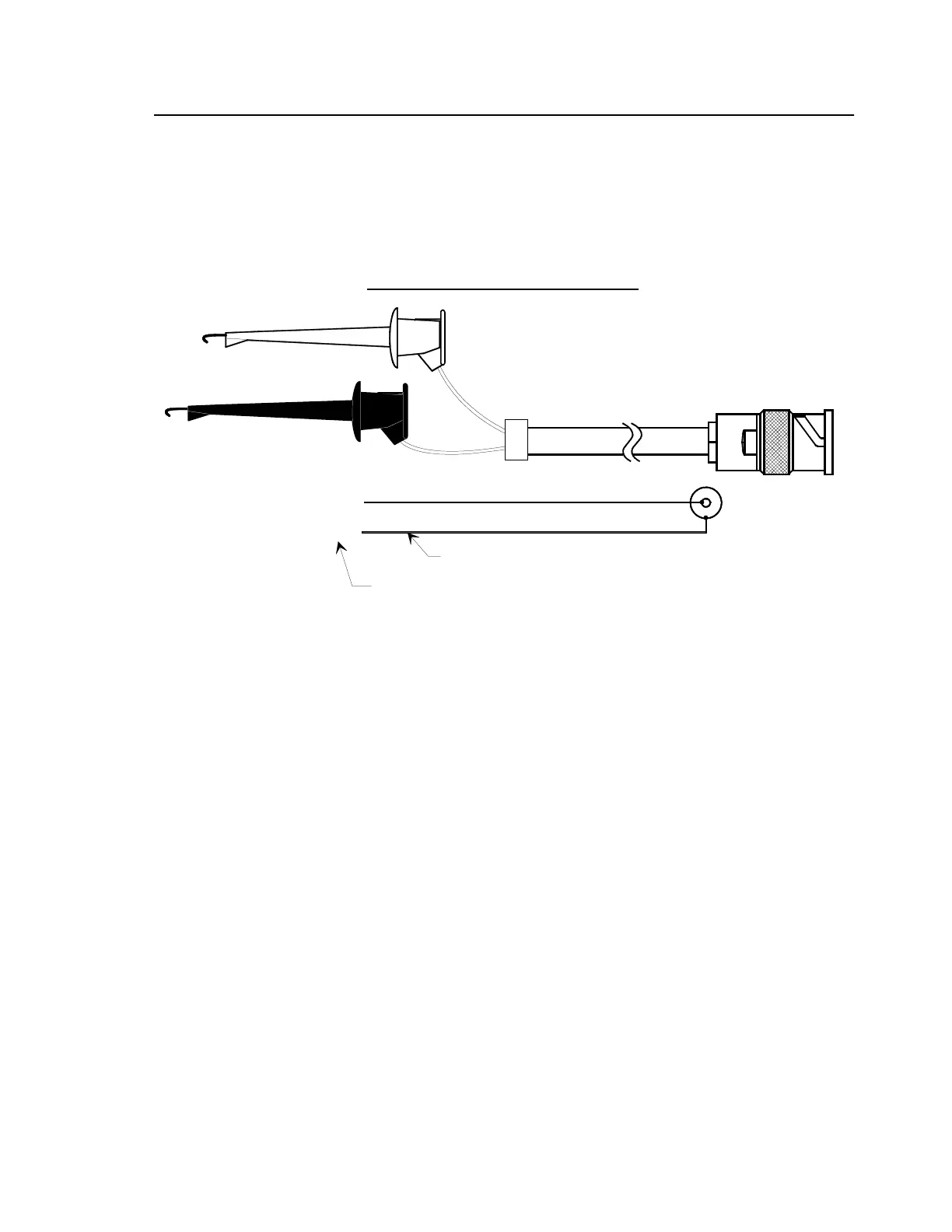
good idea to attach connector pins to the test clips; this way, the pins are easily inserted into holes in
the 8520C-36 connectors. To test a particular channel, insert the red test clip pin into the appropriate
hole in the 8520C-36 channel connector; insert the ground test clip pin into the “P” hole in the same
connector. In this manner, you can use a signal generator to simulate signals or perform the calibration
tests in Section 5.5.
Figure A-8. 8520C-36 Test Cable Schematic
8520C-36 Test Cable, Test-Clip-to-BNC
SHIELD
RG-58 Coax Cable
FILENAME: TESTC36B.DRW
RED CLIP, "SIGNAL"
BLACK CLIP, "P"
LABEL TEST CLIPS AS SHOWN
MALE BNC
CONNECTOR

 Loading...


