5-48 Chadwick-Helmuth A Business Unit of Honeywell International, Inc.
Chapter 5 - Maintenance And Repair
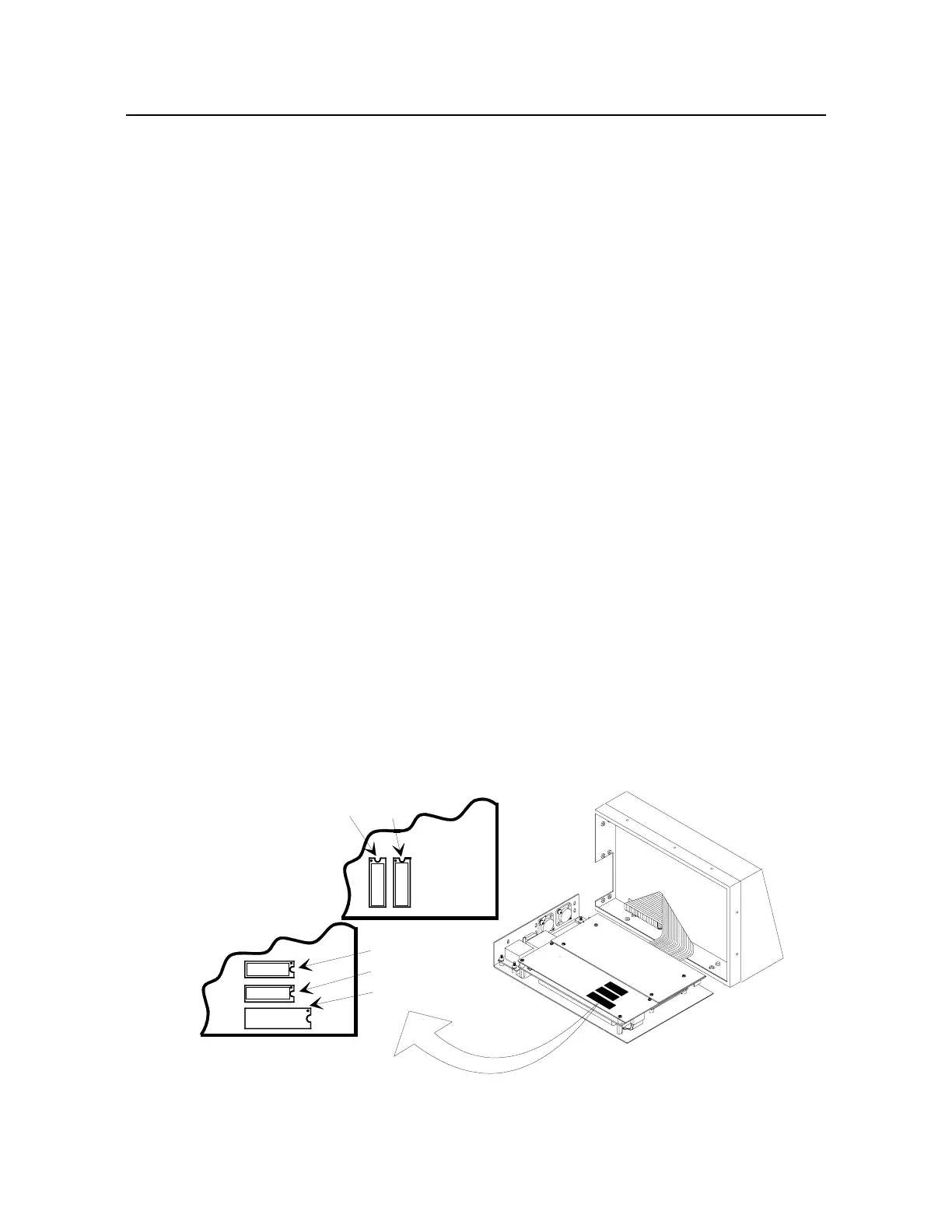
5.7.3 EPROM Change Procedure (Figure 5-15)
NOTE: The firmware in the 8500C+ is changed through a programming disk and does not
require the unit to be opened. The EPROMS are shown here in the event the device fails.
This procedure is for changing EPROM’s (U8) and (U9) on the digital board (A1) of the balancer/
analyzer assembly. The program code (“firmware”) that operates the unit is contained in these
EPROM’s, so over the life of the 8500C balancer/analyzer, this part may be changed several times as
features are added.
This procedure is best performed by a qualified electronics technician, but if the procedure is followed
precisely and with care, it can be done by any person generally familiar with electronic equipment.
Precautions against a static discharge to the EPROM are the most critical part of this procedure.
5.7.3.1 Preparation
Prepare a static-free work area. If you don’t have access to a static-free work station with a grounded,
conductive table top and a grounded wrist strap, the following will suffice.
On a normal wood or plastic table top, cover a one-half to one-meter-square area with aluminum foil
taped down at the edges. Touch the foil with your bare hand and set the 8500C balancer/analyzer and
the EPROM container on the foil. During the entire procedure, do not grab any materials not in contact
with the foil, especially sheets of paper or plastic. During the entire procedure, keep your skin in
contact with the foil by leaning on a bare elbow.
Tools required: one small Phillips-head screwdriver and one small straight-blade screwdriver.
5.7.3.2 Procedure
a. Remove ten screws (Figure 5-17, (32)) and four screws (33) and remove bezel (4).
b. Fold back printer/disk drive assembly so that it stands straight up on its side with keypad
panel (1) lying flat on table. With unit in this position, 2 EPROM’s (Figure 5-15, (U8) and
(U9)) are accessible on face-up side of digital board A1 (Figure 5-17). A paper label
covers center portion of each EPROM. Label for (U8) is stamped with P/N 10927-X and
(U9) is stamped with P/N 10928-X.
Figure 5-15. EPROM Locations on Digital Board
U10
U9
U8
DIGITAL BOARD A1
NOTE: NOTCHED ENDS ON EPROMS MUST BE IN DIRECTION SHOWN. LEFT ENDS OF EPROMS U8 & U9 MUST
BE ALIGNED WITH U10. U8 & U9 MAY DIFFER IN SIZE.
FILE: EPROMSA.DS4
10927-X
10928-X
U9
U6
8500C
8500C+
+

 Loading...


