D-4 Chadwick-Helmuth A Business Unit of Honeywell International, Inc.
Appendix D - 8520CS Signal Selector
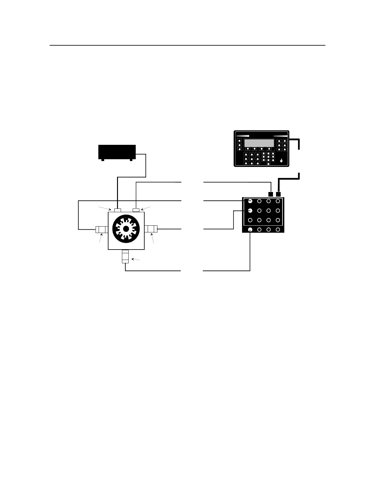
D.5.1.1 Test Setup
a. Connect equipment as shown in Figure D-2.
b. Adjust gap between magnetic pickup and screw to .04 in.
NOTE: Make sure calibrator Velocimeter cables are free to move so that Velocimeter
movement is not inhibited.
Figure D-2. Functional Test Setup (with Magnetic Pickup)
D.5.1.2 Power-Up Self-Test
a. Hold down START key on 8500C/C+ and turn on power supply.
NOTE: This erases all memory in 8500C/C+.
b. Wait until Power-Up Self-Test display appears and release START key.
VELOCIMETER
7310
VELOCIMETER
7310
MAGNETIC
PICKUP
3030
NOTE: The calibrator must have no more than one screw installed on its rotor
disk when used with the 8500C; however, the calibrator was designed to have at
least two screws 180 degrees apart. To simulate a second screw, enter the
actual rpm (half the "CAM RATE") as the balance frequency and "2" as the times
factor in the 8500C balance setup display. For example, if the CAM RATE is
900, enter "450" as the balance frequency and "2" as the times factor.
NOTE: 11B users, bypass
mag pulse doubler and
connect magnetic pickup
cable directly to channel A
on 8520C. This simulates
11A use.
Y
BALANCER/ANALYZER
CHADWICK
HELMUTH
E L M O N T E , C A L I F O R N I A
MODEL 8500C
D
J
P
BALANCE
TRACK
#
%
:
SPECTRUM
E
HELP
LOAD
STORE
K
<
Q
>
F
L
R
STATUS
SETUP
-
/
.
PRINT
A
SHOW/HIDE
B
MORE/KEYS
C
STOP
W
Z
X
START
1
4
3
6
G
M
S
7
H
2
N
5
8
T
0
V
I
O
9
U
ANNOTATE
8500C BALANCER/ANALYZER
POWER SUPPLY 9100A
CALIBRATOR 11A
POWER
BALANCER
A
B
CD
2
3
4
5
6
7
8
9
10
11
12
1
CABLE 11210
CABLE 10808
CABLE 11210
CABLE 10813
CABLE 10811
8520CS SIGNAL SELECTOR

 Loading...


