Chapter 4
8500C/8500C+ System Maintenance Manual 4-1
4.
System Theory of Operation
Section 4.1 System Description............................................................................................4-1
Section 4.2 Detailed Description.........................................................................................4-2
4.1 System Description
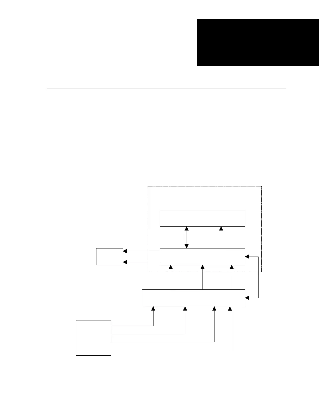
A system block diagram is shown in Figure 4-1. The balancer/analyzer assembly acquires, displays,
processes, and analyzes vibration data for fault analysis and balance correction. The printer/disk drive
assembly loads, stores, and prints vibration and related data. The Signal Selector 8520C selects
vibration and pickup signals to send to the 8500C/C+.
Figure 4-1. 8500C/C+ Balancer/Analyzer System Block Diagram
PRINTER/DISK DRIVE ASSEMBLY
BALANCER/ANALYZER ASSEMBLY
SIGNAL SELECTOR
8520C
BALANCER/ANALYZER/
PRINTER/DISK DRIVE 8500C
12-28 VDC
12-28 VDC
CONTROL
STROBEX
135M-12
AIRCRAFT
UNDER TEST
12-28 VDC
VIBRATION INPUT
MAGNETIC/PHOTOCELL PICKUP INPUT
DATA,
CONTROL,
& STATUS
FILE: FIG4-1.DRW
FASTRAK OPTICAL TRACKER

 Loading...


