Fire Alarm Control Panel IQ8Control C / M
70 FB 798951.10.GB0 / 04.15
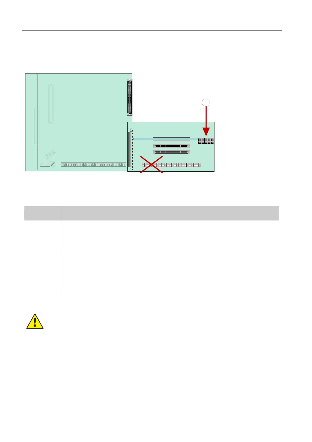
The esserbus
®
PLus cable is directly connected to the terminals on loop module (Part No. 804382 / 804382.10 /
804382.D0)
Example:
1
esserbus
®
PLus cable
terminal
(Part No.
804382 / 804382.10 /
804382.D0)
The cable screen must
be connected to the
mantle terminal (inside
panel housing).
Fig. 61: esserbus
®
PLus cable terminal
(Part No.804382 / 804382.10 / 804382.D0)
Requirements components for the esserbus
®
PLus loop:
Part No Description
802426 Power supply module with selectable 27.5 V / 42 V loop voltage
27,5 V
for esserbus
®
or
42 V
for esserbus
®
PLus
804382 /
804382.10 /
804382.D0
Loop module for esserbus
®
PLus connection.
max. 4 loop modules per Fire Alarm Control Panel (see table chapter 7.1.3)
It is only permitted to connect suitable devices for the higher loop voltage 42 V e.g.
transponders or fire detectors with Part No. 80xxxx to the esserbus
®
PLus loop
Damage to the system !
esserbus
®
PLus must be installed with the appropriate loop devices. Mixed operation of standard
esserbus
®
and esserbus
®
PLus with one control panel is not possible because the higher loop
voltage of 42 V.
The loop devices compatible with esserbus
®
PLus are indicated by the Part No. 80xxxx.

 Loading...