Honeywell MAXPRO Intrusion MPIP2000U/3000U Series Installation and Setup Guide
800-23044 Rev. A draft_11 53
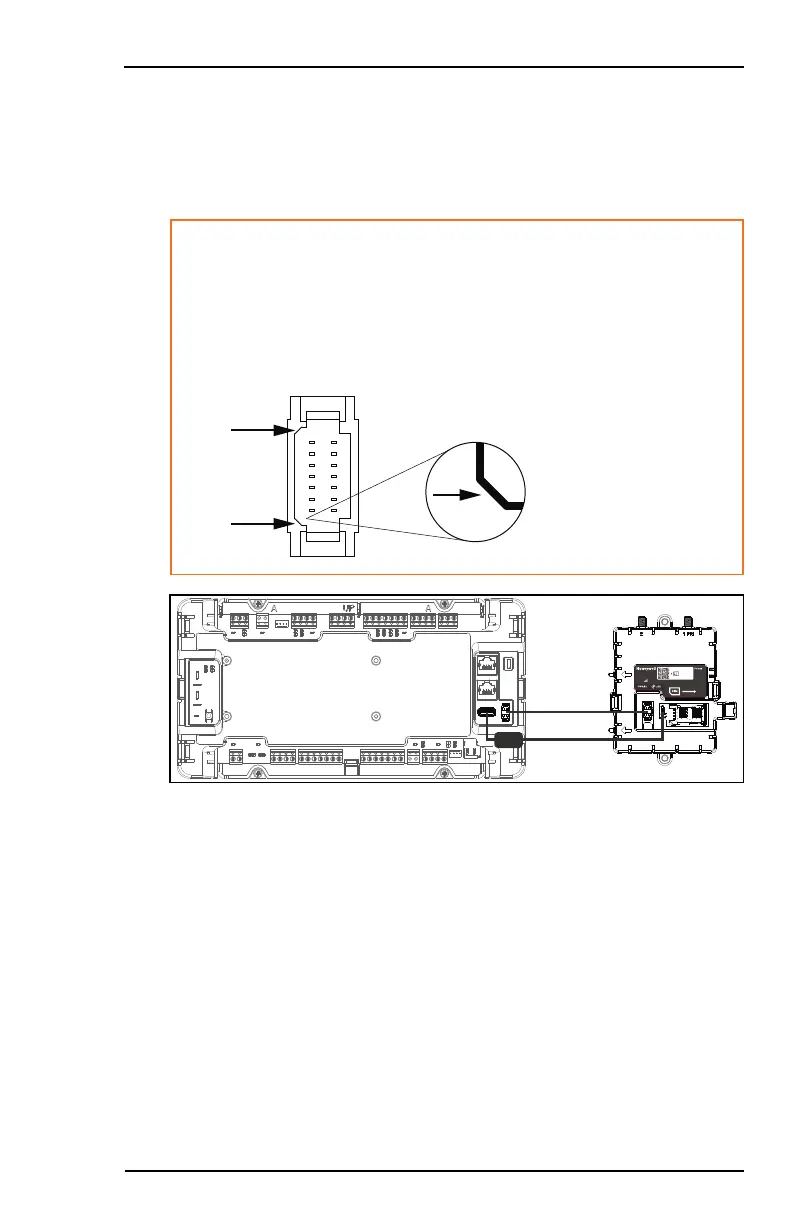
4.2.5 Connecting to the MPI Control Panel
To connect the 4G/LTE module to the control panel, proceed as follows:
1. Connect the module's PWR/IO and USB connectors (F and G) to the
MPI Control Panel using the included cables.
Caution!
Insert the plugs into the PWR/IO connectors very gently; do
not apply any pressure if the plugs don't enter immediately. If
you do apply pressure, you will bend the pins in the connectors.
Make sure to align the chamfered corners of plug and
connector correctly:
4G/LTE CELL RADIO
Network
Connected
Slide right to open
800-24408 Rev C
2. Clip the ferrite bead over the USB cable (F). Position it as close as possible
to the USB port on the control panel.
4.2.6 Installing the SMA Isolators on the MPI Cabinet
To install the SMA isolators, proceed as follows:
1. Remove the antenna knockouts from the top of the MPI cabinet (B on
page27).
2. Place the flat washer (J) on top of the cabinet knockouts, then insert the
SMA isolator (I) through the knockouts.
 Loading...