2-3
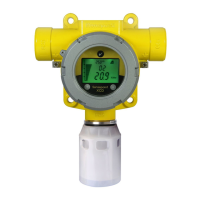
Diagram 2-3. Midas
®
display module layout
1
21
1
20
1
9
1
10
1
11
MDA Scientific Midas
1
2
1
3
1
5
1
4
1
6
1
7
1
8
1
1
1
12
1
13
1
14
1
15
1
16
1
17
1
19
1
18
2.1.2 Pump Module
The pump module is located at the back of the
main chassis. It draws the gas sample from the inlet
port located at the bottom of the mounting bracket
assembly via an inline filter to the sensor cartridge
chamber located at the front of the main chassis.
The inline filter is to protect the elements after the
sensor. The sample goes from the inlet straight to
the sensor face, and then through the rest of the
flow system. The sample is then exhausted via the
exhaust port located at the bottom of the mounting
bracket assembly. The pump and filter assemblies
are designed for easy replacement. For replacement
details refer to Sections 8.2 and 8.4.
2.1.3 Sensor Cartridge Chamber
The sensor cartridge chamber is located at the front
of the main chassis below the display module. The
plug in sensor cartridge is fitted into this area which
makes the electrical connection between the sensor
cartridge and the rest of the electronics as well as
providing the chamber where the sensor cartridge
is exposed to the sampled gas. This connection is
lightly lubricated for ease of sensor replacement.
Avoid contact of sensor cartridge chamber with
contaminants (such as dust and debris). For details
of fitting sensor cartridge refer to Section 4.9.
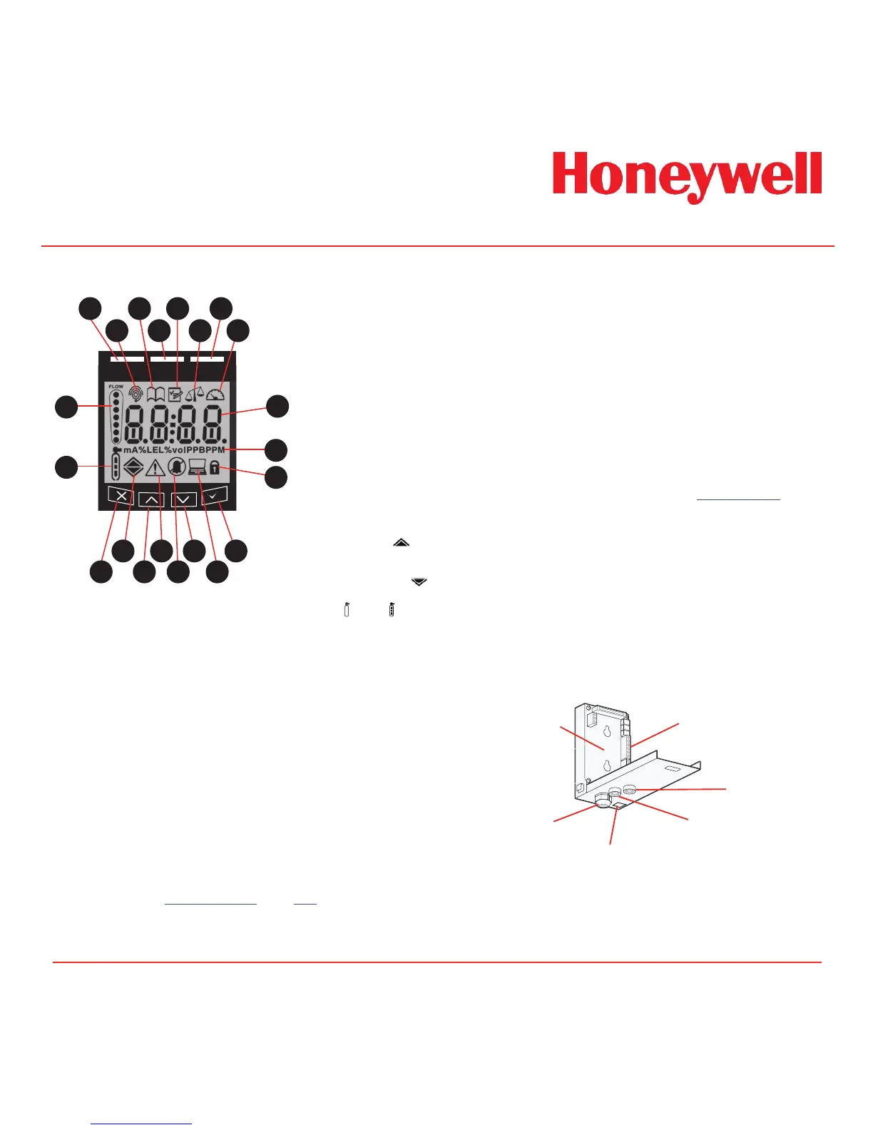
2.2 Mounting Bracket Assembly
The mounting bracket assembly comprises of the
detector mounting bracket, the terminal module, the
gas sample inlet and outlet ports, the cable/conduit
entry and Ethernet (Modbus/TCP) communications
socket.
Diagram 2-4. Mounting bracket assembly
Ethernet/PoE socket
Gas outlet port
Gas inlet port
Terminal module
Mounting bracket
Cable entry
1. Red alarm LED
2. Normal operation icon
3. Review mode icon
4. Green power LED
5. Set-up mode icon
6. Calibration mode icon
7. Yellow Fault LED
8. Test mode icon
9. Gas concentration and
message display area
10. Displayed units
11. Pass code icon
12. Accept button
13. Network icon
14. Down button
15. Inhibit icon
16. Fault icon
17. Up button
18. Alarm level 1 icon s
Alarm level 2 icon
(For flammable and toxic)
Depletion level 1 icon t
Depletion alarm level 2
19. Cancel button
20. Zero and Span calibration
icons
21. Flow indicator

 Loading...