4-11
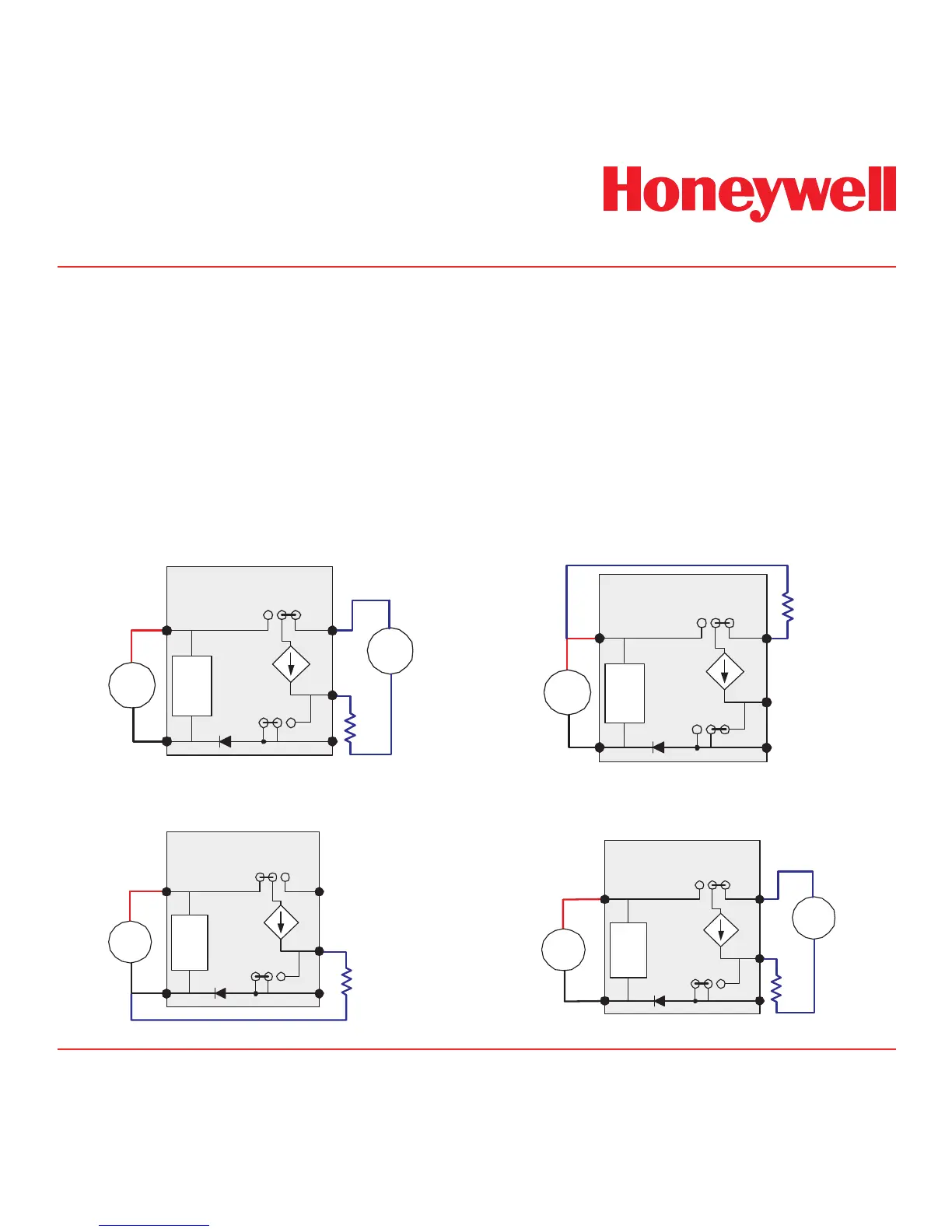
Diagram 4-7. Generic Example
Midas
®
4-Wire Isolated Output
4-20 mA
Controlled
Current Source
Internal
Power
Loads
J4
INT EXT
J5
EXT INT
11
10
9
MIDAS
Simplified Internal Schematic
2
1
-
+
+
-
24 VDC
+
-
24 VDC
R
Load
Diagram 4-8. Generic Example
Midas
®
3-Wire Sourcing
4-20 mA
Controlled
Current Source
Internal
Power
Loads
J4
INT EXT
J5
EXT INT
11
10
9
MIDAS
Simplified Internal Schematic
2
1
-
+
+
-
24 VDC
R
Load
Diagram 4-9. Generic Example
Midas
®
3-Wire Sinking Output
4.7 Electrical Connections
Midas
®
can be powered by either 24 VDC via
traditional discrete wiring or by approximately 48
VDC delivered through the Ethernet cable from
a PoE source. In either case the 4-20 mA analog
output can be used. This can be configured for
fully isolated operation. With 24 VDC power the
4-20 mA output can be configured for sink, source
or isolated output operations. Below are some
schematic diagrams of typical electrical connection
configurations. Specific wiring instructions for
connecting a Midas to a Honeywell Analytics Sieger
System-57
TM
are provided on pages 4-12 to 4-16.
Specific instructions for connection to a Honeywell
Analytics TouchPoint
TM
are provided on pages 4-17
and 4-18 and the HA71 on pages 4-19 and 4-20.
Note:
When wiring the Midas Transmitter to a
controller, program the controller for a 1-2
second delay before reporting to prevent
false alarms.

 Loading...