8-6
8.3 Reassembling the Detector
1. Align the PCB at the top rear of the main
chassis with the connector located at the top
of the mounting bracket assembly.
2. At the same time align the two tubes at the
bottom rear of the main chassis with the two
tubes located on the bottom of the mounting
bracket assembly.
3. Slide the chassis backwards on the mounting
bracket assembly so that the PCB, connector
and tubes engage simultaneously.
4. Ensure the PCB, connector and tubes are fully
engaged by firmly pushing the main chassis
horizontally backwards on the mounting bracket
assembly.
(WARNING: DO NOT PUSH ON THE LCD AS
THIS MAY CAUSE DAMAGE).
5. Align the two attaching screws located at the
bottom of the chassis with the screw threads
on the mounting bracket assembly.
6. Tighten the screws to secure the chassis to
the mounting bracket assembly.
7. Switch the power switch on the terminal
module to the ‘on’ position.
8. Refit the detector’s cover by aligning the
slots either side with the locating tabs on the
mounting bracket assembly.
9. Push the cover horizontally until home.
10. Tighten the thumbscrew located on the front
panel.
Note
Honeywell Analytics recommends
conducting a “Flow Calibration” (See
Section 7.3 for instructions)
8.4 Filter Replacement
The internal filter (MIDAS-A-009) has been designed
for easy replacement.
The following procedure should be followed carefully
and only performed by suitably trained personnel.
1. Isolate the power to the detector.
2. Unscrew the thumbscrew located on the front
panel.
3. Remove the cover by pulling it forwards off the
main chassis.
4. Unscrew the two retaining screws located at
the bottom front of the chassis.
5. Pull the main chassis forward to disconnect it
from the mounting bracket assembly.
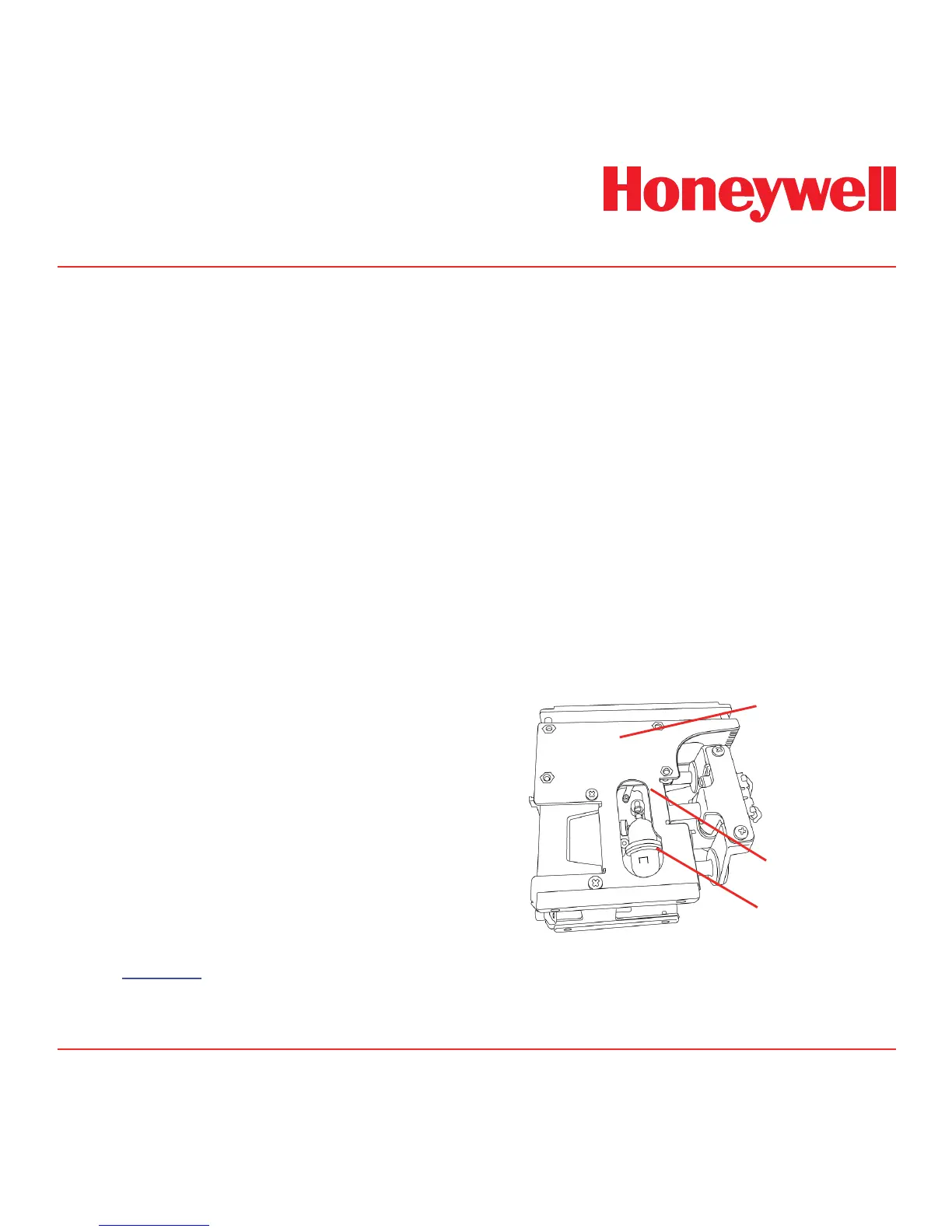
6. Locate the filter access slot in the side of the
main chassis.
Diagram 8-6. Filter location.
Main chassis
Filter
Filter access slot
7. Carefully disconnect both sides of the filter
from the pump manifold.
8. Remove the old filter and replace with a new

 Loading...