EasyManua.ls Logo

Honeywell Notifier DVC User Manual

Honeywell Notifier DVC
46 pages
To Next Page IconTo Next Page
To Previous Page IconTo Previous Page
Page #28 background imageLoading...
Page #28 background image
28 Mass Notification — P/N LS10063-000NF-E:E 06/26/2019
Programming Programming
Create MN Logic Zones
Create a logic zone that will activate if a ZF20 MN alarm comes in from any MN-mapped node.
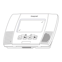
Figure 3.16 Create a Logic Sequence for the MN Active Tone
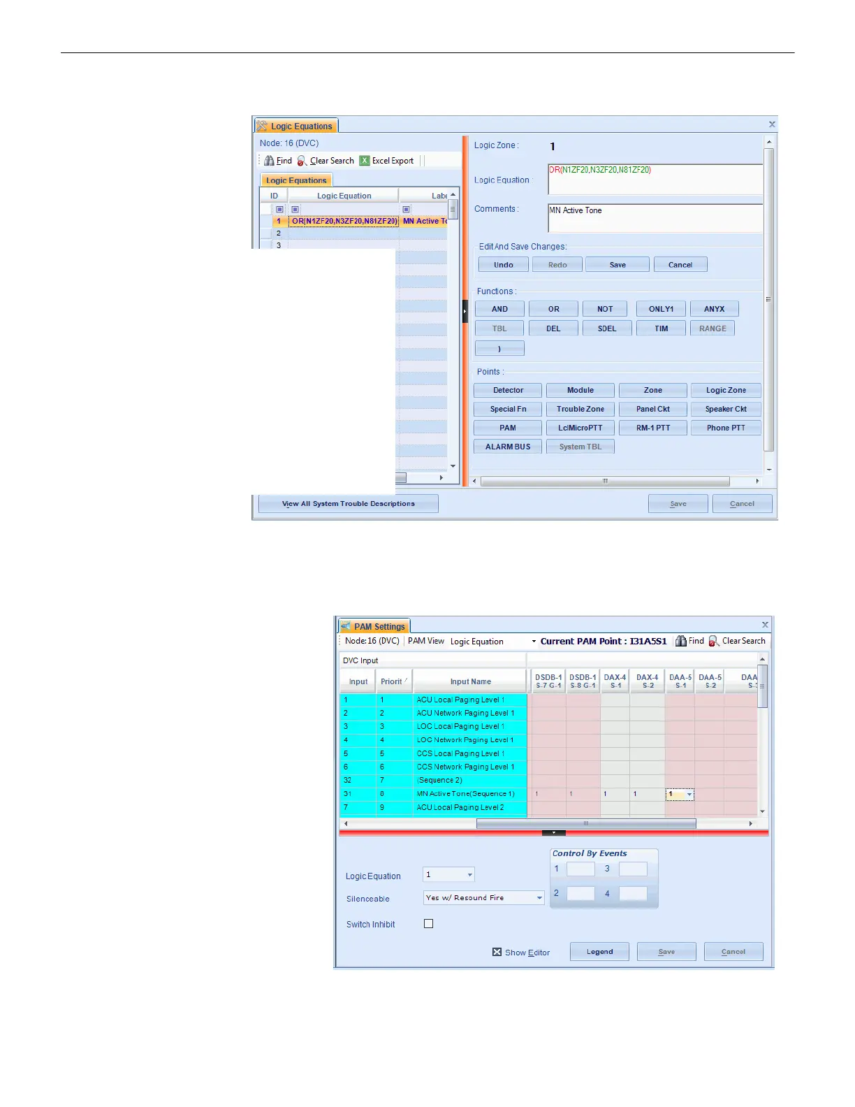
Add MN Active Tone Logic to PAM Programming
On the PAM Settings branch, add the Logic Zone created in Figure 3.16 above to the entire MN Active Tone Input row (Input 31,
Sequence 1 in this example).
Figure 3.17 Map the MN Active Tone Sequence to a Logic Zone
1. Select “OR” as the function.
2. Select “Special Function” ZF20 as the point,
and link it to each MN-mapped node on the
system.
3. Close the equation with a parenthesis, and
save changes.
4. Add label “MN Active Tone” (optional.)
5. In this example, ZL1 is the Logic Zone
programmed to activate when a ZF20 MN
alarm comes in from any MN-mapped node.
All MN-mapped nodes must be included in
the logic equation. In this example, there are
three in the system, so all three are in the
equation.
Add the MN Active Tone logic
equation to the entire Input row
for the MN Active Tone
Sequence.
In this example, Logic Zone 1 is
being added to all the cells in
Input row 31.
Question and Answer IconNeed help?

Do you have a question about the Honeywell Notifier DVC and is the answer not in the manual?

Honeywell Notifier DVC Specifications

General IconGeneral
TypeDigital Voice Command
Operating Temperature32°F to 120°F (0°C to 49°C)
CompatibilityNotifier Fire Alarm Control Panels
Operating Voltage24 VDC nominal
Current DrawStandby: 120 mA, Alarm: 250 mA
Humidity Range10% to 93% non-condensing
LED IndicatorsPower
Relay Contacts2 Form C relays
CertificationsFM, CSFM, MEA

Summary

Section 2: Configurations

2.1 Autonomous Control Unit (ACU)

Describes the primary local control unit for a mass notification system.

2.2 Local Operating Console (LOC)

Details the console used by authorized personnel to initiate messages and signaling.

2.3 Central Control Station (CCS)

Explains the system component for emergency communication and control.

Section 3: Programming

3.3.2 Mass Notification Control Settings for the DVC

Explains how to configure MN control settings on the DVC.

3.3.3 Set the Priority

Guides on setting the priority between fire and mass notification events.

3.3.4 MN Mapping

Defines how MN mapping determines fire suppression based on MN alarm status.

Section 4: Operation

4.1 Mass Notification Events

Details how MN events signal locally and over the network.

4.2 Performing a System Reset

Explains the procedure for resetting the system with fire and MN events present.

4.3 Output Event Suppression

Lists factors for achieving desired event suppression in MN systems.

Related product manuals