67
MAN0530 Issue 09 October 03 Searchline Excel
2104M0506
4. CROSS-DUCT EXCEL
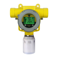
4.5.3 Connections using DX100 (M)
16
1
6
TB2
TB1
black (0V)
green/yellow (earth)
blue (B)
orange (A)
white (4-20mA)
red (+24VDC)
+24VDC in
Modbus A
4-20mA - out
Modbus B
Screen - Modbus Drain
0VDC - in
Cable shield
Instrument (clean)
earth
DX100 (M) Junction Box
Cross-Duct
Receiver
connections
Control cabinet
connections
Cross-Duct
Transmitter
connections
green/yellow (earth)
black (0V)
red (+24VDC)
The earth bonding arrangement must
ensure that the maximum peak voltage
between the unit case earth and any field
cable conductor is less than 350V.
Voltages in excess of this can cause
permanent damage to the unit’s RFI
protection filters.
Safety/
protective
ground
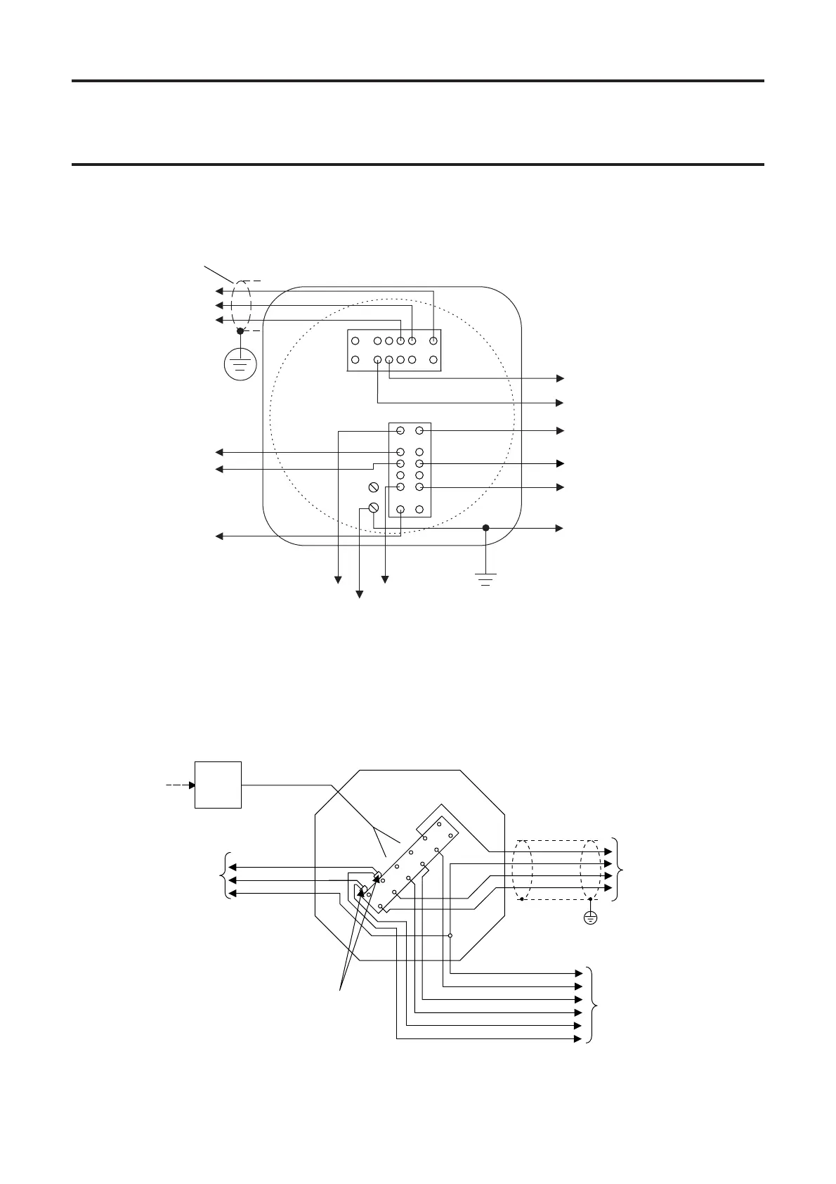
4.5.4 Connections using Non DVC/DX100/DX100 (M) Junction Box
BRN
Earth Terminal
Cable
Earth
Shield
ExdorExe
Junction Box
Flying
lead
(temporary
connection)
SHC
Protection
Device
4-20mA
2-wire
crimp ferrules
Black 0V
Red +24V
Green/ GND
4-20mA
GND
0V
+24V
Controller
Connections
Transmitter
Connections
Receiver
Connections
BLU
A
B
GRN/YEL GND
WHITE 4-20mA
ORANGE A
BLUE B
RED +24V
BLACK 0V
SHC1

 Loading...