EXTERNAL MODULATION
(cont)
Amplitude
Modulation
Suppressed Carrier
Note
that
the Reduce
Input
light
will
be ON during Suppressed Carrier operations
and should be ignored. The carrier is suppressed whenever the modulating signal is
offset
by approximately -1VDC
(+
1V
if
function
invert
is asserted). The DC corn-
ponent
of
the modulating signal controls the amplitude
of
the
carrier
from
inverted
carrier
(-2V
offset)
to
suppressed carrier (-1V
offset)
to
normal carrier
(+
OV
off-
set). The Reduce
Input
light
and
"E50"
are inhibited
while
in either
of
the
cf>
Lock
modes
when
the
phase locked loop is unlocked.
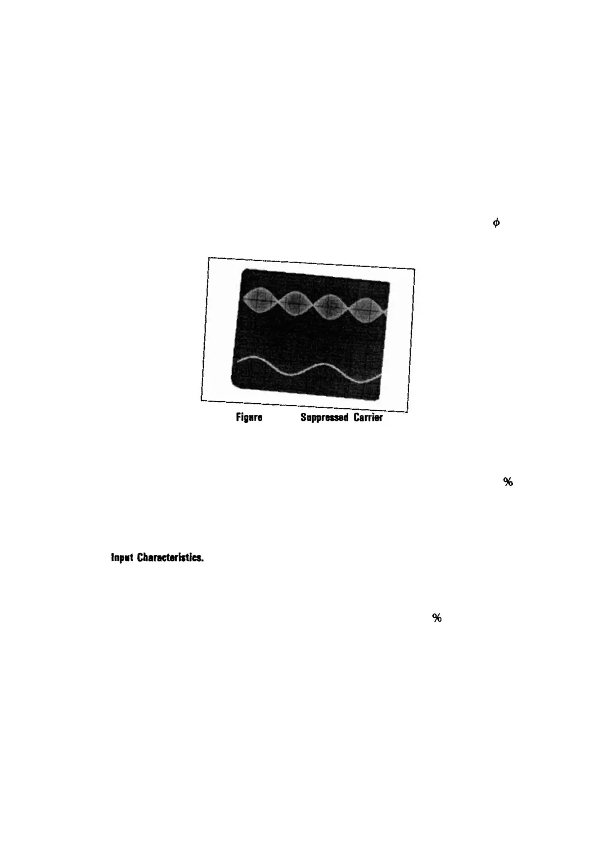
Figlr8 6.
AM
Sappreaed
Carrier
Frequency
Modulation
The
3314A's
output
signal can be Frequency
Modulated
to
deviations
of
± 1%
of
the
frequency range. The sense
of
the FM
input
is
not
affected
by
Function Invert.
The deviation is
constant
for
all carrier frequencies in
the
same frequency range as
long as
the
modulating signal is constant.
FM
Inplt
CIIal'lCtlristJcs.
The FM
input
has
the
following
characteristics (all values are
approximate):
Input
Impedance . . . . . . . 1
OkO
Input
Sensitivity
2Vp-p
= ± 1%
of
freq range
(+
1Vpeak = + 1
%)
(-1Vpeak = -1
%)
Modulation
. . . . . . . . . . . . . . . 0 to ± 1% deviation
3dB Bandwidth . . . . . . . . .
100Hz
to
100kHz
(AC coupled)
58
I
I

 Loading...


