Model
864
2A/B
Installation
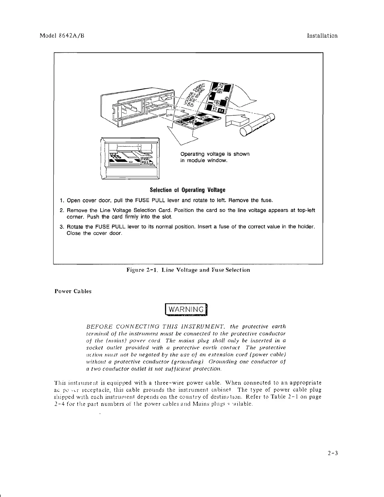
Operating voltage is shown
in
module window.
Selection
01
Operating
Voltage
1.
Open cover door, pull the FUSE PULL lever and rotate
to
left. Remove the fuse.
2. Remove the Line Voltage Selection Card. Position the card so the line voltage appears at top-left
corner. Push the card firmly into the slot.
3.
Rotate the FUSE PULL lever
to
its normal position. Insert a fuse
of
the correct value
in
the holder.
Close the cover door.
Figure
2-1.
Line
Voltage
and
Fuse
Selection
Power
Ca bles
I WARNINGI
BEFORE
CONNECTING
THIS
INSTRUMENT.
the
protective
earth
terminal
of
the
instrument
must
be
connected
to
the
protectIve call ductal'
of
the
(maills)
power
cord
The
maillS plug shall oilly
be
inserted
in
a
socket
outlet
provided
with a
protective
earth
contact
The
protective
[((Iio/l
must
//0/
be
negated
by
the
use
oj
all
extension
cord
(power
cable)
without
a
protective
conductor
(groullding).
Grounding
one
cOl!ductor
oj
a
two
conductor
outlet
is
not
sufficient
protectio/!.
This
Instrument
is
equipped
with
a
three-wire
power
cable.
When
connected
to
an
appropriate
at.:.
PI..'
.cr
Ict..:cptac!e, this
cable
grounds
the
instrument
cahinet
The
type
of
power
cable
plug
shipped
WIth
each
instnllllcnl
depends
OIl
the
coulltry
of
destin,dloll.
Refer
t,)
Table
2-\
011
page
2-4
for
the
part
numbers
01
the
power
cables
and
l\fains
plUgs
'I
·"ilable.
2-3
 Loading...