22
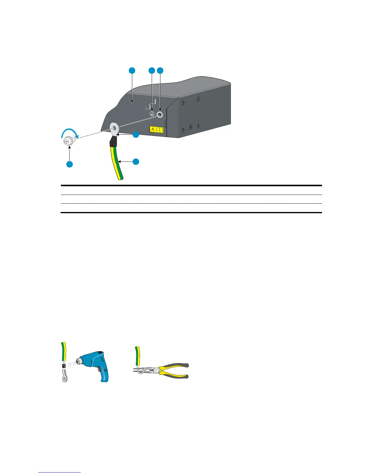
2. Attach the grounding screw to the OT terminal of the grounding cable.
3. Use a screwdriver to fasten the grounding screw into the grounding screw hole.
Figure 27 Connect the grounding cable to the grounding hole of the switch
4. Remove the hex nut of a grounding post on the grounding strip.
5. Cut the grounding cable as appropriate for connecting to the grounding strip.
6. Make the connector on the grounding cable:
If you have an OT terminal, follow callout A in Figure 28 to make the connector: Peel 5 mm (0.20
in) of insulation sheath by using a wire stripper, and insert the bare metal part through the black
insulation covering into the end of the OT terminal. Secure the metal part of the cable to the OT
terminal with a crimper, cover the joint with the insulation covering, and heat the insulation covering
with a blow dryer to completely cover the metal part.
If you do not have an OT terminal, follow callout B in Figure 28 to make the connector: Peel the
insulation sheath by an appropriate length with a wire stripper, and then bend the naked metal
part.
7. Connect the connector to the grounding strip, and fasten it with the removed hex nut. See Figure 29.
Figure 28 Make the grounding cable connector
 Loading...