4
(4) LINK LED for a combo interface
(6) Port LED mode switching (Mode) button
(10) ACT LED for a combo interface
Rear panel
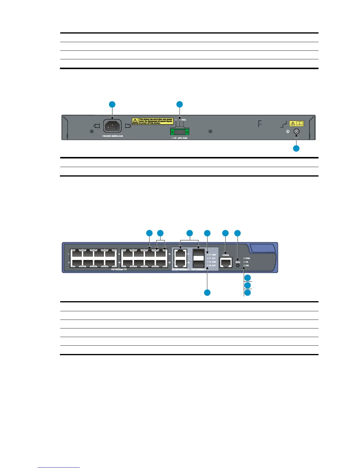
Figure 8 A3100-24-PoE v2 EI rear panel
(1) AC-input power receptacle
(2) DC-input terminal block
A3100-16-PoE v2 EI
Front panel
Figure 9 A3100-16-PoE v2 EI front panel
(1) 10/100Base-TX Ethernet port
(2) 10/100Base-TX Ethernet port LEDs (left: yellow, right: green)
(3) Combo interface (10/100/1000Base-T Ethernet port on the left, 100/1000Base-X SFP port on the right)
(4) LINK LED for a combo interface
(6) Port LED mode switching (Mode) button
(10) ACT LED for a combo interface
 Loading...