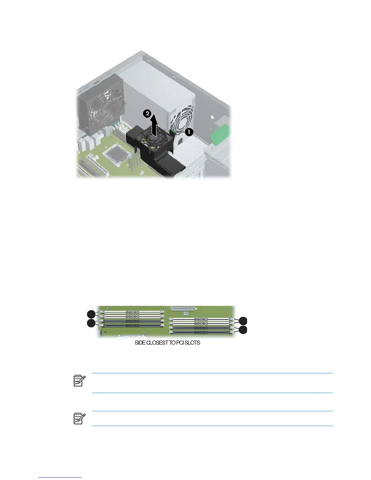
2. Depress the green tabs on the memory fan housing (1) and lift the unit out of the chassis (2).
Figure 4-17 Removing the memory fan
3. Gently push out on the socket levers.
4. Prepare to load memory modules in valid configurations:
●
DIMMs must be loaded in matched pairs.
●
If loading two DIMMs, install them in slots 1a/1b.
●
If loading four DIMMs, install them in slots 1a/1b and 2a/2b for a dual CPU system, or in 1a/
1b and 3a/3b for a single CPU system.
●
If loading six DIMMs, install them in slots 1a/1b, 2a/2b, and 3a/3b.
●
If loading eight DIMMs, install them in all slots.
●
Load the memory module pairs in order of size, from largest to smallest.
2
4
1
3
Figure 4-18 Identifying memory slots
5. Lower the DIMM straight down, and be sure the socket levers secure the module into place.
NOTE DIMMs and DIMM sockets are keyed for proper installation. Be sure these guides
align when installing a DIMM.
6. Lower the memory fan until it snaps into place.
NOTE Ensure that all cables are clear of the fan housing when lowering the memory fan.
72 Chapter 4 Removal and replacement procedures ENWW
 Loading...