LP-605 Rev. 000 Rel. 009 Date 8.16.18
23
F. Temperature and Pressure Relief Valve
To avoid water damage or scalding due to relief valve operation:
• Discharge line must be connected to relief valve outlet and
run to a safe place of disposal. Terminate the discharge line
in a manner that will prevent possibility of severe burns or
property damage should the relief valve discharge.
• Discharge line must be as short as possible and the same
size as the valve discharge connection throughout its entire
length.
• Discharge line must pitch downward from the valve and
terminate at least 6” above the oor drain, making discharge
clearly visible.
• Discharge line shall terminate plain, not threaded, with a
material serviceable for temperatures of 375
o
F or greater.
• Do not pipe discharge to any location where freezing could
occur.
• No shuto valve may be installed between the relief valve
and water heater or in the discharge line. Do not plug or place
any obstruction in the discharge line.
• Test the operation of the relief valve after lling and
pressurizing the system by lifting the lever. Make sure the
valve discharges freely. If the valve fails to operate correctly,
replace it with a new relief valve.
• Test relief valve at least once annually to ensure the waterway
is clear. If valve does not operate, turn the water heater “o”
and call a plumber immediately.
• Take care whenever operating relief valve to avoid scalding
injury or property damage.
• For water heaters installed with only a pressure relief valve,
the separate storage vessel must have a temperature and
pressure relief valve installed. This relief valve shall comply
with Relief Valves for Hot Water Supply Systems, ANSI Z21.22
CSA4.4.
FAILURE TO COMPLY WITH THE ABOVE GUIDELINES COULD
RESULT IN FAILURE OF RELIEF VALVE OPERATION, RESULTING
IN POSSIBILITY OF SUBSTANTIAL PROPERTY DAMAGE, SEVERE
PERSONAL INJURY, OR DEATH.
RE-INSPECTION OF RELIEF VALVES: Valves should be inspected
AT LEAST ONCE EVERY THREE YEARS, and replaced if necessary,
by a licensed plumbing contractor or qualied service technician
to ensure that the product has not been aected by corrosive
water conditions and to ensure that the valve and discharge line
have not been altered or tampered with illegally. Certain naturally
occuring conditions may corrode the valve and its components
over time, rendering the valve inoperative. Such conditions can
only be detected if the valve and its components are physically
removed and inspected. Do not attempt to conduct an
inspection on your own. Contact your plumbing contractor for a
re-inspection to assure continued safety.
Do not thread a cap or plug into the relief valve or relief valve
line under any circumstances! Explosion and property damage,
serious injury, or death may result.
FAILURE TO RE-INSPECT THE RELIEF VALVE AS DIRECTED
COULD RESULT IN UNSAFE TEMPERATURE AND/OR PRESSURE
BUILD-UP WHICH CAN RESULT IN PROPERTY DAMAGE,
SERIOUS PERSONAL INJURY, OR DEATH.
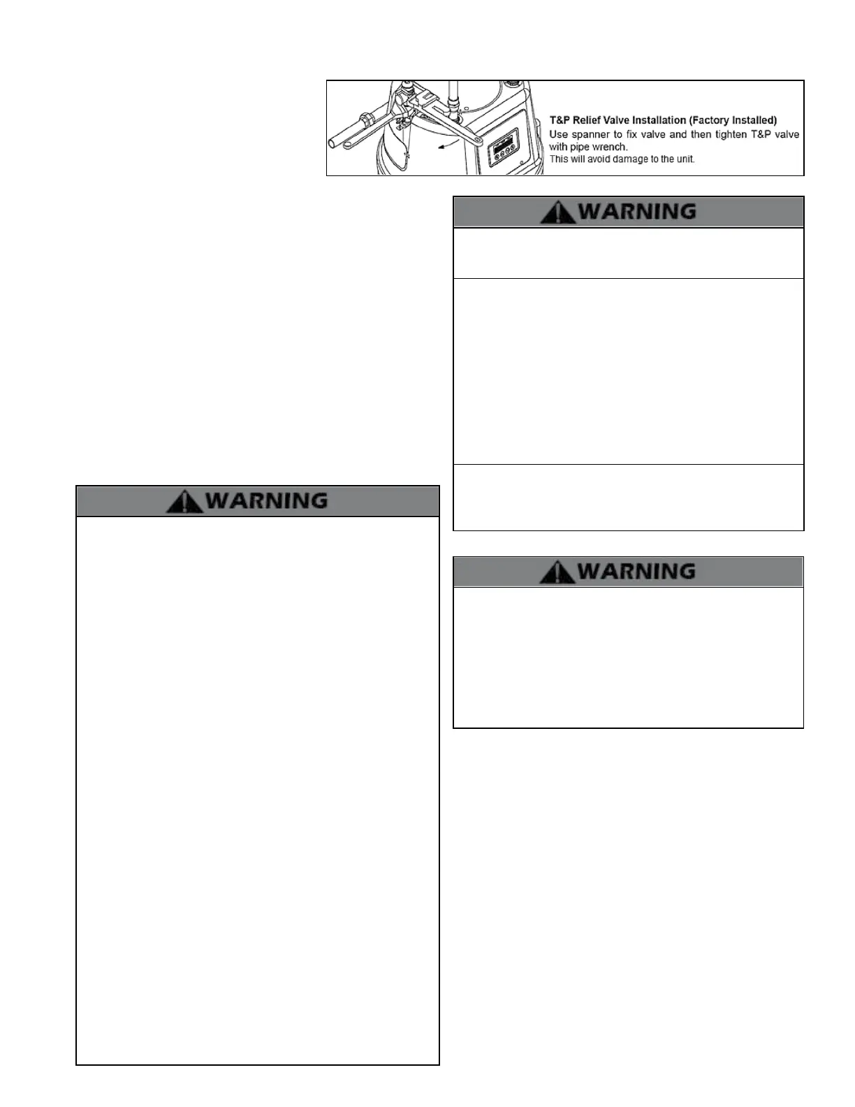
Figure 17 - Relief Valve Installation Details
An external pressure relief valve must be
installed on this water heater. When installing,
observe the following guidelines. Failure to
comply with these guidelines can result in
substantial property damage, personal injury,
or death.
This water heater must be provided with an
approved 150 psi, ¾” ASME HV Valve that
must be installed on the DHW outlet line (See Figure 17). The 150
psi Pressure Relief Valve must be installed on the DHW supply line to
ensure a compliant installation and safe operation.
This water heater has a high-temperature shut-o switch built in as
a standard safety feature. Therefore, a “pressure only” relief valve
is required. DO NOT operate this water heater before the supplied
pressure relief valve is installed with sucient relieving capacity in
accordance with the ASME rating plate on the water heater.
Pressure relief valves must be installed as close to the water heater as
possible. No other valves should be placed between the pressure relief
valve and the appliance. DO NOT install a relief valve with a pressure
rating greater than 150 psi. This is the maximum allowable relief valve
setting for this water heater.
After installing the relief valve and lling and pressurizing the system,
test the operation of the valve by lifting the lever. Make sure the valve
discharges freely. If the valve fails to operate correctly, replace it with
a new relief valve. Ensure that the maximum BTU/H rating on the
pressure relief valve is equal to or greater than the maximum input
BTU/H rating of the combination water heater.
The water heater must be full of water and the system fully purged
BEFORE powering the water heater. When lling the water heater,
open a hot water tap to release air in the water heater and piping.
All air has been purged from the system when water runs freely
from the faucets.
Applying power to the water heater when it is not full of water will
damage the heat exchanger, and could result in property damage,
serious personal injury, or death. Such damages ARE NOT covered
by water heater warranty.
G. Filling the Heater
• Ensure any drain valves are completely closed.
• Open the shut-o valve in the cold water supply line.
• Open the hot water faucets to allow air to vent from the
heater and piping.
• Allow sucient time for the heater to completely ll with
water.
H. Draining the Water Heater
1. Close water supply shut-o valve to the water heater.
2. Connect garden hose to the drain valve located on the lower
left side of the unit.
3. Open the valve with a at heat screwdriver.
4. After draining the tank, turn the drain valve body clockwise
by hand to remove the drain valve from the unit and clean the
lter.

 Loading...