LP-605 Rev. 000 Rel. 009 Date 8.16.18
44
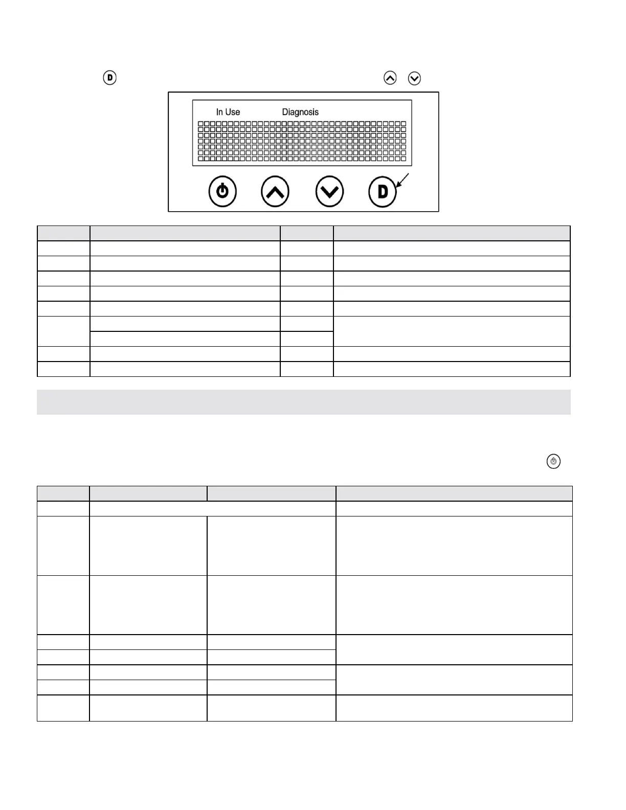
Figure 46 - Press the “D” Button to Review Diagnostic Functions
Display Detail Example Description
Ver Main CPU Software Version Ver: 1 Current version of software running on the PCB
Ht Hot Water Stored / Tank Temperature Ht: 145 Tank temperature is 145
o
F
Ot Outlet Temperature Ot: 134 Outlet temperature is 134
o
F
Gpm Water Flow Rate into Tank 1.2 Current water ow rate into tank is 1.2 gpm
Rpm Fan RPM Rp 4500 Fan is spinning at 4500 RPM
H
Burner Time Hours 2h
Total burn time is 2 hours, 10 minutes, and 14 seconds
Burner Time Minutes and Seconds 10m 14s
T Ignition Cycles 7T Seven total ignition cycles
E1 - E9 Error Code History E1: E4 The most recent error stored is E1. E9 is the oldest.
F. Diagnostic Button Function
The water heater control allows the user to review various diagnostic functions, including: Outlet Temperature, Fan RPM, and Error Code
History. Press the button on the display to review various diagnostic functions. Press the or buttons to scroll through the functions.
Table 26 - Diagnostic Function Screen Descriptions
A. Error Code Screens
The water heater continuously monitors its own operation. If an error occurs a message will scroll across the display on the front panel and
an error code will display. These error codes assist in troubleshooting system issues, and may enable the user to overcome a problem without
calling for service. If calling Technical Support for assistance, please reference the displayed error code to aid in troubleshooting. Press to
turn the water heater OFF and ON to reset an error code.
Error Code Description Cause Possible Remedies
E1 Abnormal Flame Detected Call for service. Replace the main controller.
E2 Ignition Failure
Water heater does not detect a
ame signal.
1. Check gas line, ignitor, ame rod.
2. Check wire connection of 22p wire and ignitor wire.
3. Check ignition noise. If fuel supply is low ignition will
make noise.
4. Check gas type and manifold pressure.
E3 Flame Loss
Abnormal combustion - Flame
has been lost after it was
detected.
1. Check the gas supply.
2. Check the gas valve.
3. Check wire connection fo 22p wire and ignitor wire.
4. Check gas type and pressure.
5. Check power supply for proper voltage.
E4 Outlet Thermistor Open Outlet thermistor is open.
1. Check the outlet thermistor.
2. Check wire connection of 22p wire and thermistor wire.
E5 Outlet Thermistor Short Outlet thermistor has shorted.
E6 Tank Thermistor Open The H/E thermistor is open.
1. Check the H/E thermistor.
2. Check wire connection of 22p wire and thermistor wire.
E7 Tank Thermistor Short The H/E thermistor has shorted.
E11 Blower Motor
The DC blower motor has
failed.
1. Check the DC blower motor.
2. Check wire connection of 22p wire.
Part 10 - Troubleshooting

 Loading...