LP-605 Rev. 000 Rel. 009 Date 8.16.18
40
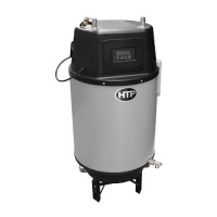
5. Reassemble the top service panel and apply the LP label which is
in the accessory kit.
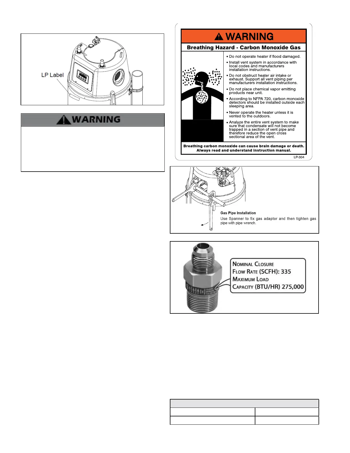
Figure 42 - Excess Flow Valve (EFV)
Prior to start-up, ensure the unit is set to re on propane. Check
the rating label for the type of fuel. Use a calibrated combustion
analyzer to ensure the CO / CO2 limits are within the limits listed
in Table 24. If there is a conict or doubt on the setup, remove
the gas tube and check for the propane orice. Failure to ensure
proper setup could result in property damage, severe personal
injury, or death.
C. Gas Connection Requirements
1. The gas connection tting on the water heater is ¾” female
NPT. NOTE: A 3/4” X 1/2” reducer is provided with the water
heater for connection to 1/2” gas lines. It is important to
review the gas table to ensure that the gas line is properly
sized for the BTU output of the water heater.
NOTE: DO NOT USE 1/2” quick ex gas lines! Doing so will
result in improper appliance operation.
2. The supply line must be sized for the maximum output of
the water heater being installed. If there are additional gas
appliances from the main supply line, measure the size of
the supply line according to the COMBINED total maximum
BTUH draw for the appliances as if they were operating at
the same time.
3. Measure the length of the gas supply line from the gas
meter to the water heater. Water heater must be installed
downstream of the gas meter to ensure adequate gas
supply. Use the tables in this manual or refer to the gas line
manufacturer’s sizing information to determine the correct
supply pipe size.
4. A manual gas shut-o valve should be installed in the gas
supply line close to the water heater.
5. To facilitate any future maintenance, it is also recommended
that an approved gas union tting be installed in the supply
line between the shut-o valve and the connection on the
water heater.
6. Test the gas pressure to make sure it meets the minimum
standards and does not exceed the maximum standards of
the water heater.
7. Leak test the gas line pipe before placing the water heater in
operation. Only use approved leak detector liquid solutions
to check for leaks.
8. Do not operate the water heater until all connections have
been completed and the heat exchanger is lled with water.
Figure 40 - Reassembled Top Service Panel and Applied LP Label
D. Additional Precaution for Excess Flow Valve (EFV)
If an excess ow valve (EFV) is in the gas line, check the manufacturer’s
minimum and maximum ow capacity ratings. An improperly sized
EFV will not allow for a full ow of gas to the water heater and will
cause the water heater to malfunction. See Figure 43.
Figure 41 - Installing the Gas Line to the Water Heater
E. Checking Gas Pressure at the Water Heater
NOTE: Refer Figure 44 when checking gas pressure. Loosen the bolts
before checking the gas inlet pressure.
1. The water heater and its individual shuto valve must be
disconnected from the gas supply piping system during any pressure
testing of the system at test pressures greater than ½ psi (3.5 kPa).
2. The water heater must be isolated from the gas supply piping system
by closing its individual manual shuto valve during any pressure
testing of the gas supply piping system at test pressures equal to or
less than ½ psi (3.5 kPa).
The minimum and maximum inlet gas line pressures must meet the
requirements shown in Table 23.
Natural or LP Gas
Minimum Pressure 3.5” WC
Maximum Pressure 14”WC
Table 23 - Gas Pressure Requirements

 Loading...