LP-605 Rev. 000 Rel. 009 Date 8.16.18
27
E. Exhaust Vent and Intake Pipe Sizing
1. The exhaust vent and intake pipe adapters are 3”.
2. The total equivalent length of 3” exhaust vent and intake pipe
should not exceed one hundred (100) feet (30m).
a. The equivalent length of elbows, tees, and other ttings are
listed in the Friction Loss Table.
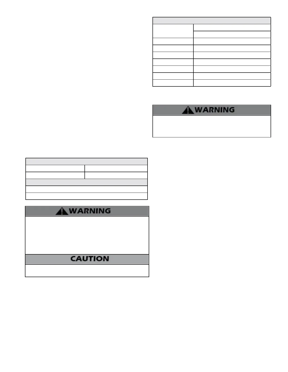
Friction Loss Equivalent in Piping and Fittings
Fittings or Piping
Equivalent Feet
3”
90 Degree Elbow 5’ (1.5m)
45 Degree Elbow 3’ (0.9m)
Coupling 0’
Air Inlet Tee 0’
Straight Pipe 1’ (0.3m)
Concentric Kit 3’ (0.9m)
V1000 3” Kit 1’ (0.3m)
Table 10 - NOTE: Consult Polypropylene venting instructions for friction
loss and pressure drop equivalents.
b. For example: If the exhaust vent has two 90
o
elbows and 10 feet
of PVC pipe we will calculate:
Exhaust Vent Equivalent Length = (2x5) + 10 = 20 feet.
Further, if the intake pipe has two 90
o
elbows, one 45
o
elbow, and
10 feet of PVC pipe, the following calculation applies:
Intake Pipe Equivalent Length = (2x5) + 3 + 10 = 23 feet.
Finally, if a concentric kit is used we nd:
Total Equivalent Length = 20 + 23 + 3 = 46 feet.
The total equivalent length is 46 feet, well below the maximum of
150 feet.
c. Eort should be made to keep a minimum dierence in
equivalent length between the exhaust vent and intake pipe.
Vent adaptors are not designed as load-bearing devices, and must
not be used to support exhaust vent piping. All vent pipes must be
properly connected, supported, and the exhaust must be pitched
a minimum of ¼” per foot back to the boiler to allow drainage of
condensate. Failure to properly support vent piping and follow the
information in this statement could result in product damage, severe
personal injury, or death.
3. The minimum total equivalent length is 7 feet (2.1m).
NOTE: The intake pipe and exhaust vent lengths do not have to be of
equal length. There is no balancing requirement between intake and
exhaust.
It is important to ensure an airtight seal from the water heater collar to
the vent terminations. It is EXTREMELY IMPORTANT that the maximum
allowed combined venting lengths are not exceeded. See Table 8
for a list of Approved Vent Materials and Table 11 for Approved Vent
Lengths.
3” Combined Vent Length
Minimum Maximum
7’ (2.1M) 100’ (30M)
Maximum # of 90
o
Elbows
3”
8
Table 11 - Approved Vent Lengths
Failure to provide a minimum total vent length of 7 equivalent feet
could result in property damage and improper appliance operation.
G. Exhaust Vent and Intake Pipe Installation
All joints of positive pressure vent systems must be sealed
completely to prevent leakage of ue products into the living
space. Failure to do so could result in property damage, serious
injury, or death.
1. Use only solid PVC or CPVC pipe or a Polypropylene vent system
approved for use with Category IV appliances.
FOAM CORE PIPING IS NOT APPROVED FOR EXHAUST VENT
APPLICATIONS. Foam core piping may be used on air inlet piping
only.
2. Remove all burrs and debris from joints and ttings.
3. When using PVC or CPVC pipe, all joints must be properly cleaned,
primed, and cemented. Use only cement and primer approved for
use with the pipe material. Cement must conform to ASTM D2564
for PVC and ASTM F493 for CPVC pipe. NOTE: DO NOT CEMENT
POLYPROPYLENE PIPE.
4. Ensure the vent is located where it will not be exposed to
prevailing winds.
5. In all roof venting applications, exhaust discharge must point
away from the pitch of the roof.
6. To prevent water leakage, install adequate roof ashing where the
pipe enters the roof.
7. Do not locate vent over public walkways, driveways, or parking
lots. Condensate could drip and freeze, resulting in a slip hazard or
damage to vehicles and machinery.
8. Due to potential moisture build-up, sidewall venting may not
be the preferred venting option. To save time and cost, carefully
consider venting installation and location.
9. Horizontal lengths of exhaust vent must slope back towards the
water heater not less than ¼” per foot to allow condensate to drain
from the vent pipe.
10. The exhaust vent must terminate where vapors cannot make
accidental contact with people or pets, or damage shrubs or plants.
11. In vacant chimney applications, install and seal a rain cap over
existing chimney openings.
12. All piping must be fully supported. Use pipe hangers at a
minimum of 4 foot intervals to prevent sagging of the pipe where
condensate may form.
13. Do not use the heater to support any piping.
14. A screened straight coupling is provided with the heater for use
as an outside exhaust termination.
15. A screened inlet air tee is provided with the heater to be used as
an outside intake termination.
16. Maximum Snow Level Determination: These installation
instructions reference snow levels in establishing a minimum height
for the installation of exhaust vent or air intake terminations. Snow
levels shall be determined as follows:
a. The installation location may, by ordinance, designate how snow

 Loading...