LP-179 Rev. 6.7.16
25
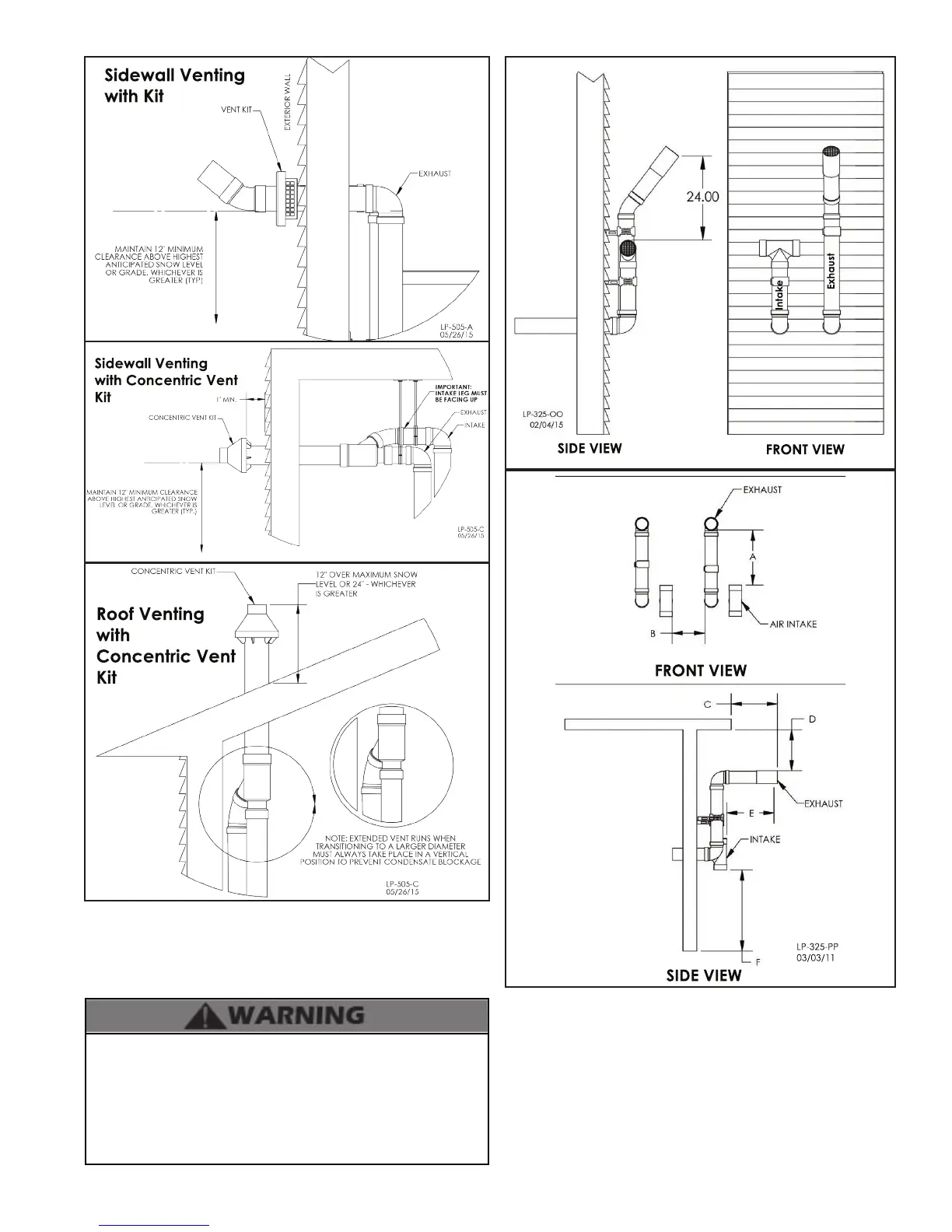
Sidewall Venting
with Kit
Sidewall Venting
with Concentric Vent
Kit
Roof Venting
with
Concentric Vent
Kit
Figure 16 - Venting with Optional Kits (NOT INCLUDED WITH THE
WATER HEATER)
NOTE: These drawings are meant to demonstrate system
venting only. The installer is responsible for all equipment and
detailing required by local codes.
All vent pipes must be glued, properly supported, and the
exhaust pitched a minimum of 1/4” per foot back to the heater
to allow drainage of condensate. When placing support brackets
on vent piping, the rst bracket must be within 1 foot of the
water heater and the balance of 4 foot intervals on the vent
pipe. Venting must be readily accessible for visual inspection
from the rst three feet from the heater.
NOTES:
A. For every 1” of overhang, the exhaust vent must be located 1”
vertical below overhang (overhang means top of building structure
and not two adjacent walls [corner of building]).
B. Typical installations require 12” minimum separation between
bottom of exhaust outlet and top of air intake.
C. Maintain 12” minimum clearance above highest anticipated snow
level or grade (whichever is greater).
D. Minimum 12” between vents when installing multiple vents.
E. 12” minimum beyond air intake.
SIDE VIEW
FRONT VIEW
Intake
Exhaust
FRONT VIEW
SIDE VIEW
LP-325-PP
03/03/11
Figure 17 - Horizontal (Snorkel) Venting

 Loading...


