LP-179 Rev. 6.7.16
35
1. Connect the outdoor sensor to the terminals marked
“outdoor”.
2. Press and hold S3. An alternating du and temperature value
will appear on the display. Set du to the maximum desired tank
temperature (default 119
o
F). After setting the temperature,
press S3 to exit the menu.
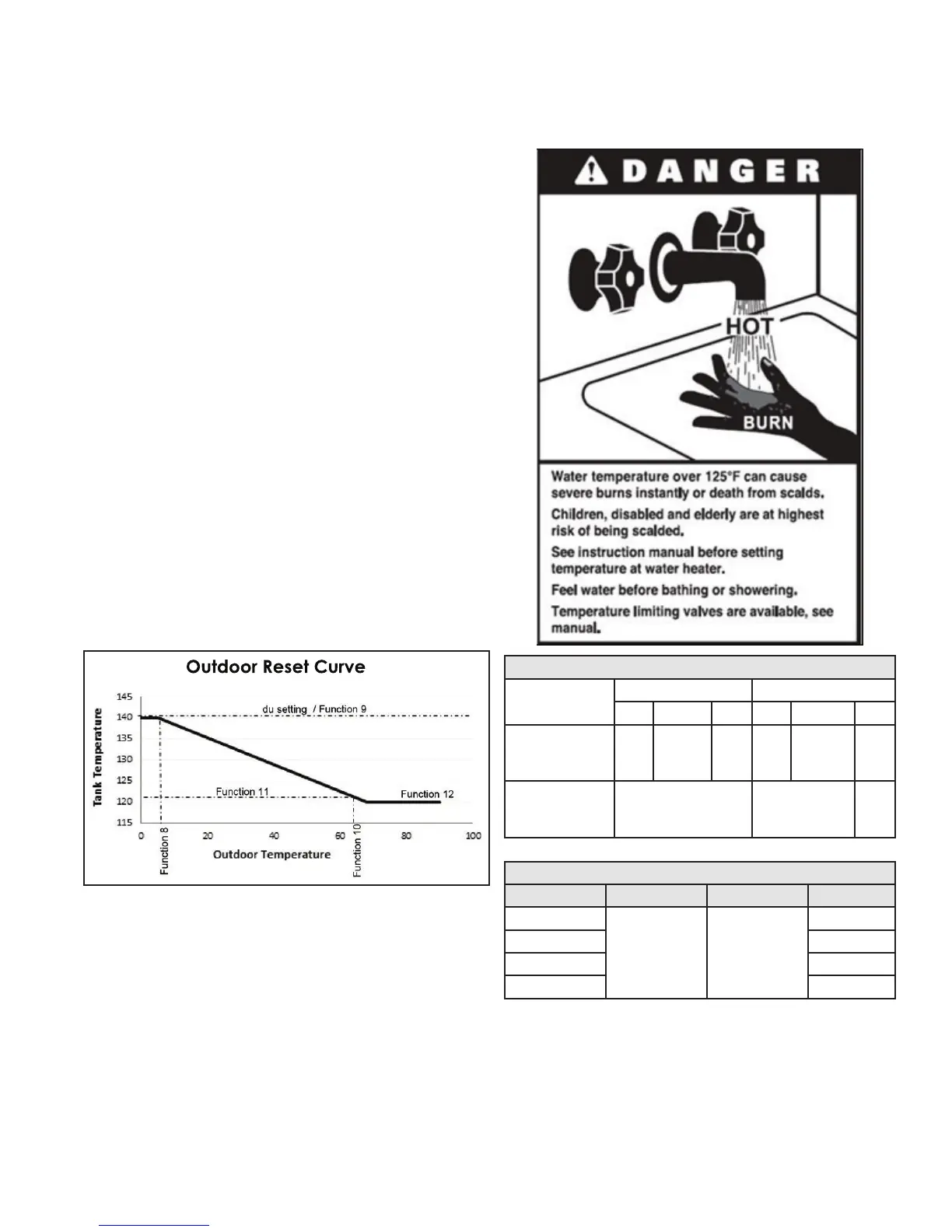
3. Setting the outdoor reset curve (change only the functions
listed in the descriptions below):
a. Press and hold S3 and S4 together for 5 seconds.
b. Use S1 and S2 to adjust the ashing 000 to code 975.
Press S3 until you enter the menu.
c. Use S3 to scroll to Function 8 to adjust minimum outdoor
temperature. Use S1 and S2 to adjust temperature to desired
setting (Range: -49
o
F - 32
o
F / Default 5
o
F).
d. Use S3 to scroll to Function 9 to adjust maximum water
heater storage temperature. Use S1 and S2 to adjust
temperature to desired setting (Range: 77
o
F - 160
o
F / Default
119
o
F). NOTE: Function 9 must match the du setting.
e. Use S3 to scroll to Function 10 to adjust maximum outdoor
temperature (warm weather shutdown temperature). Use
S1 and S2 to adjust temperature to desired setting (Range:
32
o
F - 95
o
F / Default 68
o
F).
f. Use S3 to scroll to Function 11 to adjust minimum water
heater storage temperature. Use S1 and S2 to adjust
temperature to desired setting. This temperature must be
set to the maximum desired DHW temperature (Range: 32
o
F
- 160
o
F / Default 159
o
F).
g. Use S3 to scroll to Function 12 to adjust desired DHW
temperature (minimum tank temperature). Use S1 and S2 to
adjust temperature to desired setting (Range: 32
o
F - 160
o
F /
Default 95
o
F).
h. Press and hold S4 to exit the menu.
Figure 28 - NOTE: The maximum tank temperature is 160
o
F,
independent of all settings described above.
E. Test Mode
This function is intended to simplify gas valve adjustment if
necessary. Listed on the following page are recommended
limits on each heater and the combustion settings. Automatic
modulation does not take place when the controller is in Test
Mode, only temperature limitation based on the heater set
point. Fan speed can be increased or decreased by pressing
either S1 or S2.
To activate Test Mode, press S2 and S3 simultaneously for 1
second. Once activated, Ser will display and alternate with the
actual fan speed. The measurement of the combustion levels
should always be taken at the highest and lowest fan speed.
When in Test Mode, the heater’s limit will shut down the burner
Combustion Settings on All Models
Fan Speed
Natural Gas (NG) Propane (LP)
Low Ignition High Low Ignition High
Carbon
Monoxide (CO)
PPM
1-10 2-15 2-20 1-10 2-15 2-20
Carbon Dioxide
(CO
2
)
%
8-10 8 1/2- 10 1/2 9-11
Table 13 - Combustion Settings - All Models
Fan Speeds
BTU Ignition Min Max
100,000
3000 2000
5700
130,000 7300
160,000 7450
199,000 9100
Table 14 - Fan Speeds
F. Maintenance
The control system requires no periodic maintenance under
normal conditions. However, in unusually dirty or dusty
conditions, periodic vacuuming of the cover to maintain
visibility of the display and indicators is recommended. In dirty
environments, such as construction sites, care must be taken
to keep the water heater burner cover in place and drywall or
saw dust away from water heater.
if temperature limit is exceeded. It is recommended to draw
water out of the tank to lower temperature so tests can be
performed.
After 10 minutes, Test Mode stops automatically. To exit Test
Mode, press S1 and S2 simultaneously for 1 second.

 Loading...


