LP-179 Rev. 6.7.16
29
Part 6 - Wiring
To avoid electrical shock, turn o all power to the heater prior
to opening an electrical box within the unit. Ensure the power
remains o while any wiring connections are being made.
Failure to follow these instructions could result in component or
product failure, serious injury, or death. Such product failure IS
NOT covered by warranty.
Jumping out control circuits or components WILL VOID product
warranty and can result in property damage, personal injury, or
death.
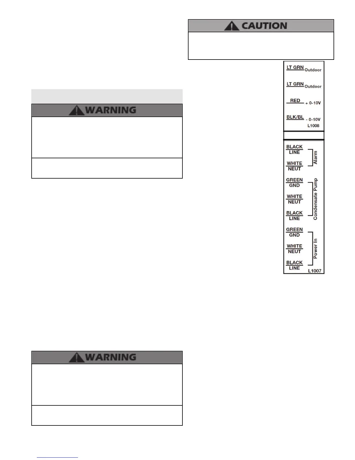
A. Line Voltage Input
The heater must be wired to a 120 volt circuit by a qualied
electrician. It is recommended that the heater be wired on its
own circuit to minimize the possibility of circuit failure due to
outside clauses. The heater requires a maximum of 8 amps at
120 volts in use.
B. Line Voltage Condensate Output
The heater has the capability of supplying power to a condensate
pump. The connection is 120 VAC +/- 10% at a max of 2 amps.
Power is supplied to the pump only when the heater is connected
to power, and the power switch is in the on position.
C. Low Voltage Outdoor Sensor Input
The heater has the capability of an outdoor reset. Connecting
an outdoor sensor allows the heater to operate at optimum
eciency. HTP oers an outdoor sensor, p/n 7250P-319.
The outdoor sensor must be a 12K NTC sensor. Use a minimum
22 AWG wire for runs of 100 feet or less and minimum 18 AWG
wire for runs up to 150 feet. Instructions are included with the
outdoor sensor to correctly mount the sensor on the exterior
surface of the building. It is preferable to mount the sensor
on the north side in an area that will not be aected by direct
sunlight but will be exposed to varying weather conditions.
Connect the outdoor sensor to terminals marked “Outdoor”.
It is of extreme importance that this unit be properly grounded. It
is very important that the building system ground is inspected by
a qualied electrician prior to making this connection. Electrical
power must only be turned on when the heater is completely
lled with cold water. Failure to follow these instructions could
result in component or product failure, serious injury, or death.
Label all wires prior to disconnecting them when servicing
the heater. Wiring errors can cause improper and dangerous
operation. Failure to follow these instructions may result in
property damage or personal injury.
D. Alarm Connections
The control includes an alarm
output. This circuit is rated at 3 amps
at 120 volts. This contact can be used
to activate an alarm light or bell
or notify a building management
system if the water heater goes into
a lockout condition.
E. Optional 0-10 Volt Building
Control Signal
A signal from a building
management system may be
connected to the water heater to
enable remote control. This signal
should be a 0-10 volt positive-
going DC signal. When this input is
enabled using the installer menu, a
building control system can be used
to control the set point temperature
of the water heater. The control
interprets the 0-10 volt signal as
follows; when the signal is between
0 and 1.5 volts, the water heater
will be in stand-by mode, not ring.
When the signal rises above 1.5
volts, the water heater will ignite. As
the signal continues to rise towards
its maximum of 10 volts, the water
heater will increase in set point
temperature. See Part 10 for details
on the setting of function 16.
NOTE: During 0-10V operation, the
minimum tank temperature set point (default 95
o
F) will be at
the activation input of 1.5 volts. The maximum temperature
set point value will be at the input voltage of 10 volts. The
maximum temperature set point can be changed by increasing
or decreasing the DU setting (Range: 77
o
F – 160
o
F / Default
119
o
F). Once programmed, the 0-10V feature will change the
set point temperature automatically.
1. Connect a building management system or other auxiliary
control signal to the terminals marked 0-10 VOLT + and
0-10 VOLT – in the electronics assembly (shown in Figure
25). Caution should be used to ensure that the 0-10 VOLT +
connection does not become connected to ground.
2. Conguring the appliance for 0-10 volt operation (change
only the functions in the descriptions below):
a. Press and hold S3 and S4 together for 5 seconds
b. Use S1 and S2 to adjust ashing 000 to code 975. Press S3
until you enter the menu.
c. Use S3 to scroll to Function 16 to enable/disable 0-10 volt
operation. Use S1 and S2 to adjust display to desired setting
(Range: 0 = O, 2 = On / Default O).
d. Press and hold S4 to exit the menu.
freezing temperatures or any type of blockage. In installations
that may encounter sustained freezing conditions, the use of
heat tape is recommended to avoid freezing of the condensate
line. It is also recommended to bush up the condensate line size
to 1” and terminate condensate discharge as close to the unit as
possible. Longer condensate runs are more prone to freezing.
Damages due to frozen or blocked condensate lines ARE NOT
covered by warranty.
4. Support of the condensate line may be necessary to avoid
blockage of the condensate ow.
Figure 23 - Field Wiring
An ASSE 1017 thermostatic mixing valve MUST be installed
when using 0-10V or outdoor reset. Failure to do so could result
in substantial property damage, serious injury, or death.

 Loading...


