LP-179 Rev. 6.7.16
32
UL recognized fuel gas detectors are recommended in
all enclosed propane and natural gas applications where
there is a potential for an explosive mixture of fuel gas to
accumulate. The installation of these detectors should
be made in accordance with the detector manufacturer’s
recommendations, and/or local laws. Failure to install fuel gas
detectors in these applications could result in re, explosion,
property damage, severe personal injury, or death.
A. Gas Piping
Run the gas supply line in accordance with all applicable
codes. Locate and install manual shuto valves in accordance
with local and state requirements.
Support gas supply piping with hangers, not by the heater
or its accessories. The heater gas valve and blower will not
support the weight of the piping. Make sure the gas piping
is protected from physical damage and freezing, where
required. Failure to follow these instructions could result in
gas leakage, and result in re, explosion, property damage,
severe personal injury, or death.
Do not use Teon tape on gas line pipe thread. Use a pipe
compound rated for use with natural and propane gases.
Apply sparingly on male pipe ends, leaving the two end
threads bare. Failure to follow these instructions could result
in gas leakage, and result in re, explosion, property damage,
severe personal injury, or death.
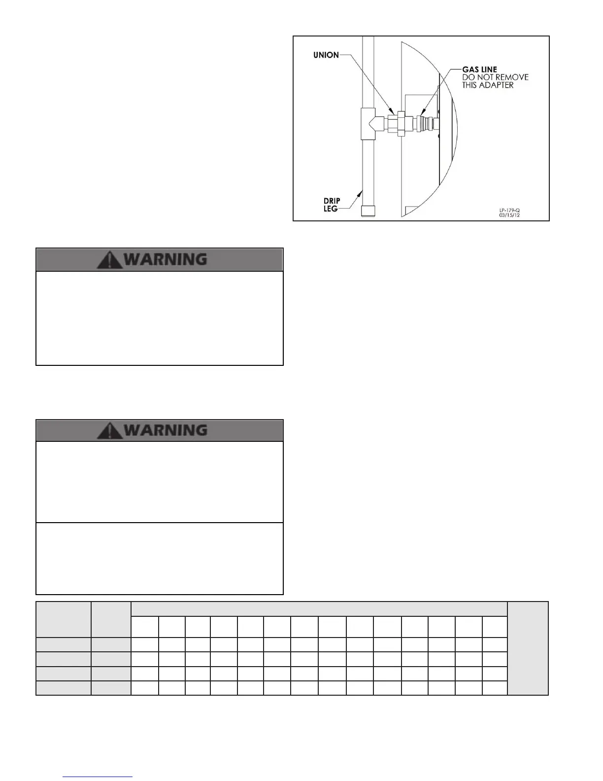
Figure 26 - Gas Connection
Nominal
Iron Pipe
Size (in.)
Internal
Dia. (in.)
Length of Pipe (Feet)
BTU’s
Per Hour
x 1,000
10 20 30 40 50 60 70 80 90 100 125 150 175 200
3/4 .824 278 190 152 130 115 105 96 90 84 79 72 64 59 55
1 1.049 520 650 285 245 215 195 180 170 160 150 130 120 110 100
1 1/4 1.38 1050 730 590 500 440 400 370 350 320 305 275 250 225 210
1 1/2 1.61 1600 1100 890 760 670 610 560 530 490 460 410 380 350 320
Table 11 - Source - ANSI Z223.1
B. Gas Table
connections must be approved by the local gas supplier or
utility, in addition to the governing authority, prior to turning
the gas supply on.
Do not remove the adaptor in Figure 26! It is mandatory that
this tting is used for connection to a eld fabricated drip leg
per the National Fuel Gas Code. You must ensure that the
entire gas line to the connection at the water heater is no
smaller than 3/4”.
Once all inspections have been performed, the piping must
be leak tested. If the leak test requirement is a higher test
pressure than the maximum gas inlet pressure, you must
isolate the heater from the gas line to continue leak testing.
To do this, you must turn o the factory and eld-installed gas
cocks. This will minimize the possibility of damaging the gas
valve. Failure to do so may damage the gas valve. In the event
the gas valve is exposed to a pressure greater than ½ PSI, 14”
water column, the gas valve must be replaced. Never use an
open ame (match, lighter, etc.) to check gas connections.
Refer to the table below to size the supply piping to minimize
pressure drop between meter or regulator and unit.
Maximum capacity of pipe in cubic feet of gas per hour for gas
pressures of .5 psi or less and a pressure drop of .3 inch water
column.
It is recommended that a soapy solution be used to detect leaks.
Bubbles will appear on the pipe to indicate a leak is present.
The gas piping must be sized for proper ow and length of pipe
to avoid excessive pressure drop. Both the gas meter and the
gas regulator must be properly sized for the total gas load. If
you experience a pressure drop greater than 1” WC, the meter,
regulator or gas line is undersized or in need of service. You can
attach a manometer to the incoming gas drip leg by removing
the cap. The gas pressure must remain between 3.5” WC and
14” WC during stand-by (static) mode and while in operating
(dynamic) mode at full output.
If an in-line regulator is used, it must be a minimum of 10 feet
from the heater. It is very important that the gas line is properly
purged by the gas supplier or utility. Failure to properly purge
the lines or improper line sizing will result in ignition failure.
This problem is especially noticeable in NEW LP installations
and also in empty tank situations. This can also occur when
a utility company shuts o service to an area to provide
maintenance to their lines. The gas valve must not be replaced
with a conventional gas valve under any circumstances. As an
additional safety feature, the gas valve in this water heater has a
anged connection to the swirl plate and blower.

 Loading...


