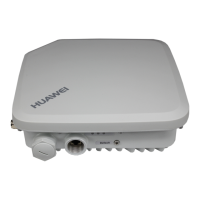
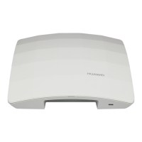
AP7052DN&AP7152DN
Hardware Installation and Maintenance Guide
Huawei Proprietary and Confidential
Copyright © Huawei Technologies Co., Ltd.
Four rubber pads are attached to specified positions on the
bottom of the AC before it is placed on a desk.
The AC is secured in the cabinet or rack by rack-mounting
brackets or guide rails (or trays), and floating nuts are
correctly secured.
The AC card is secured in the cabinet or rack by guide rails
or trays, and the guide rails or trays and floating nuts are
correctly secured.
The AC card is correctly inserted into the device slot and
secured using the ejector lever.
No pins on the backplane are bent when the AC card is
installed.
The AC is grounded using a ground cable, meeting surge
protection requirements.
When the AC directly connects to APs, location IDs of the
APs are provided at the cable connection points.
The proper PoE switch or power adapter is selected, meeting
AP power supply and onsite environment requirements.
To ensure that the PoE power meets requirements, the PoE
power supply device and APs must be connected through
CAT5E and CAT6E network cables, and the cable length
cannot exceed 100 m.
Labels must be made for the PoE power cable to identify AP
locations.
Leave a 20 cm space between PoE power adapters to ensure
normal heat dissipation.
The PoE switch is correctly grounded with the ground cable.
Reserve a few downlink network interfaces for the PoE
switch (for example, connect at most 20 APs to a 24-port
switch) for future capacity expansion.
You are advised to configure dual power modules for a PoE
switch for power redundancy backup and providing power
for more APs.
The AP installation positions comply with the network
planning report and APs cannot be installed in environments
with strong electrical or magnetic interference or corrosive
materials. If the onsite environment does not meet
requirements, adjust the AP installation positions properly.
 Loading...
