AP7052DN&AP7152DN
Hardware Installation and Maintenance Guide
Huawei Proprietary and Confidential
Copyright © Huawei Technologies Co., Ltd.
Connect multimeter probes to two ends of each wire in a network cable and check the
resistance value on the multimeter.
Connect a network cable to an AP. Use a multimeter to test the resistance between pins 1
and 2 (or between pins 3 and 6, 4 and 5, or 7 and 8) on the other end of the cable. The
cable's DC resistance approximately equals a half of the displayed value.
Table 5-13 PoE standard requirements for network cable quality
Total
Resistance of
a Network
Cable
Maximum PD power consumption <
12.95 W
Maximum PD power consumption <
25.5 W
If an AP is connected to a switch or AC (excluding ACU2), you can run the virtual-cable-test
command on the switch or AC to check network cable connectivity. For details, see the
virtual-cable-test command in the command reference.
5.1.4 Assembling Feeders
5.1.4.1 Assembling the Straight Male Coaxial N Connector and the 1/2''
Feeder
Context
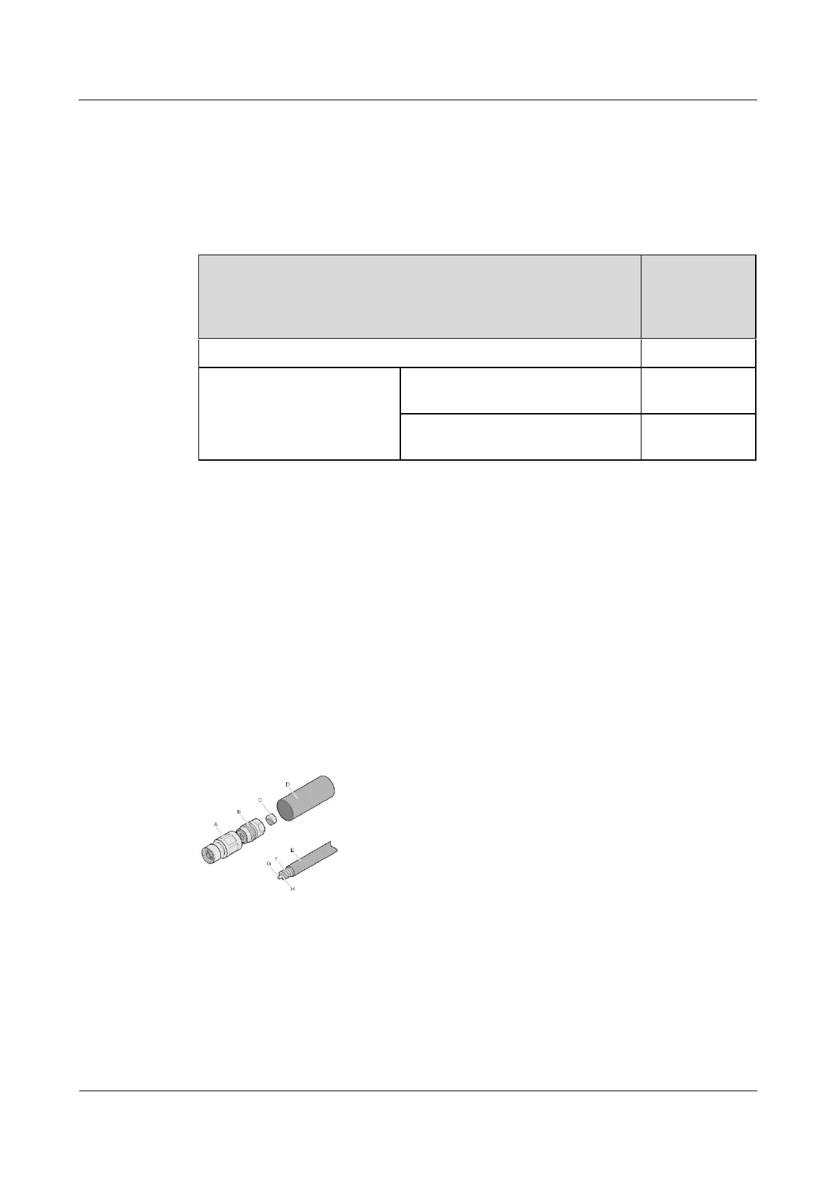
Figure 5-89 shows the components of an N coaxial connector and a 1/2" feeder cable.
Figure 5-89 Components of an N coaxial connector and a 1/2" feeder cable
B. Back shell of
connector
F. Outer conductor of
feeder cable
G. Inner conductor of
feeder cable
H. Insulation layer of
feeder cable
 Loading...