18 hunter.direct/ICC2help
Installation Instructions
Installation Instructions
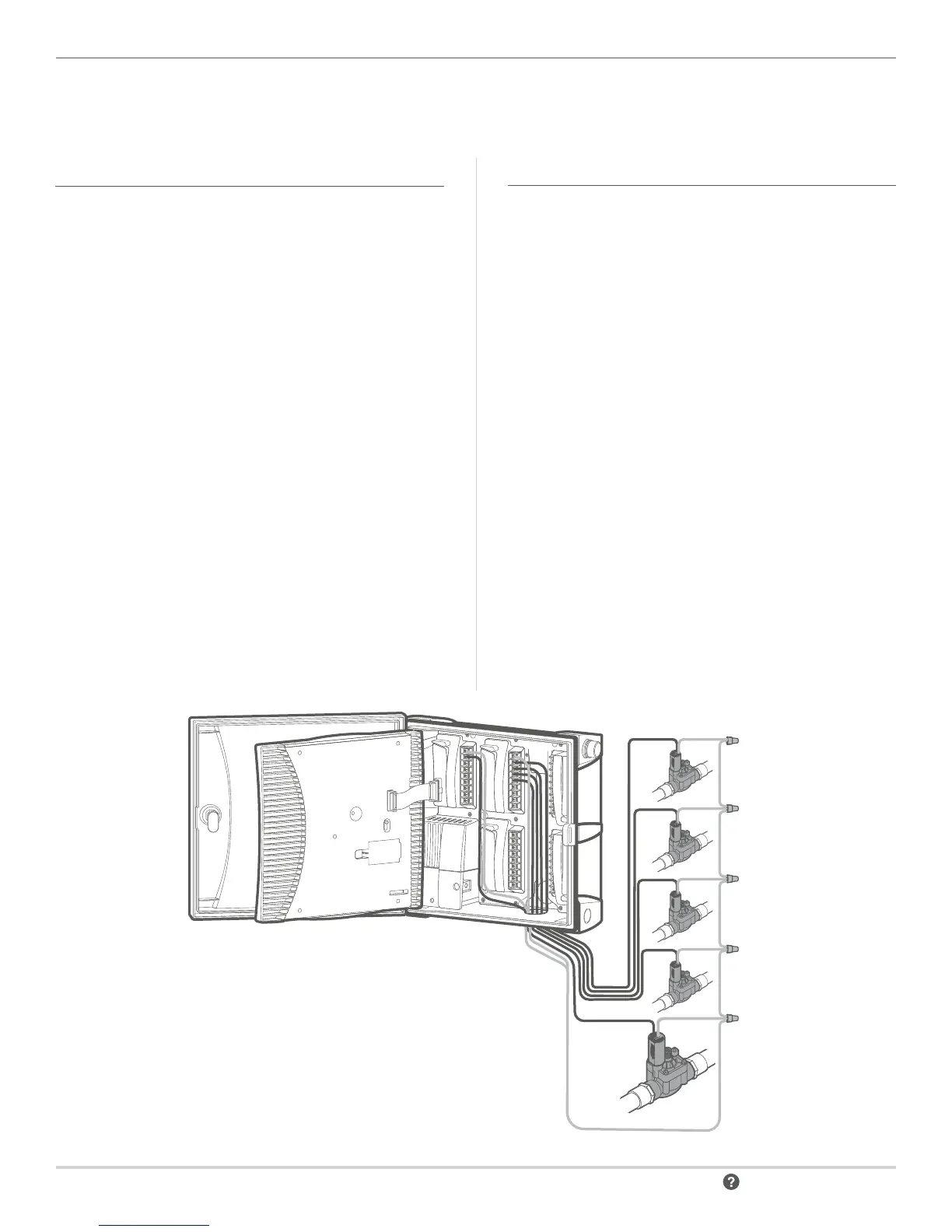
CONNECTING STATION WIRES
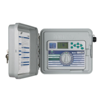
Each ICC2 controller is supplied with a factory-installed base
module for up to 8 stations (ICM-800). Multiple additional
modules may be added in increments of 4 (ICM-400),
8 (ICM-800), or one 22-station expansion module
(ICM-2200). Each station module has its own common
terminal, which runs in conjunction with the corresponding
station terminals within the module. Each station output is
rated for 0.56 A maximum, which can safely operate up to
two Hunter solenoids simultaneously.
1. Route station/valve wires between control valve and
the controller.
2. At the valve(s), attach the common wire to either
solenoid wire for each individual valve. This is most
commonly a white-colored wire. Attach a separate
control wire to the second remaining solenoid wire of
each valve. All wire splice connections should be made
using waterproof connectors.
3. Route all common and valve control wires through an
incoming conduit to the controller. The conduit can attach
to any of the knockout openings at the bottom of the
cabinet from ½" (13 mm) up to 2" (50 mm) diameter.
4. Strip ½" (13 mm) of insulation from the ends of all wires.
Secure the valve common wires to corresponding “COM”
terminals. Attach all individual valve control wires to the
appropriate station terminals.
CONNECTING A MASTER VALVE OPTIONAL
Complete this section only if you have a Master Valve
installed. The ICC2 has one Pump/Master Valve (P/MV)
output, which is capable of activating either a normally
closed Master Valve or a Pump Start Relay. A Master Valve
is typically installed at the supply point of the main line,
and opens only when the automatic system is activated.
The purpose of a Master Valve is to shut o the water to
the irrigation system when none of the station valves are
operating. It is also benecial for shutting o a system when a
zone or mainline develops a leak or break. The P/MV output is
rated for up to 0.56 A.
5. Route the Master Valve wire pair into and out of the
cabinet similarly to the station wires.
6. The P/MV output is located on the power output module,
in the upper le corner of the ICC2.
7. Connect either wire from the Master Valve to the P/MV
terminal, and connect the remaining wire to the common
“COM” terminal.
8. The Master Valve can be activated in accordance with
any particular station. The controller default setting is
to activate the Master Valve output with all stations;
however, it can also be programmed to be active or
disabled with any individual station.
 Loading...