Built on Innovation
®
21
Installation Instructions
CONNECTING A HUNTER SOLAR SYNC SENSOR
NOT INCLUDED
The Solar Sync is a smart sensor system that, when
connected to a Hunter ICC2, will automatically adjust your
programmed watering schedule based on changes in local
climate conditions. Solar Sync utilizes a solar radiation and
temperature sensor to measure on-site weather conditions
and determine evapotranspiration (ET), which is the rate at
which plants and turf use water. In addition, the Solar Sync
sensor also includes a Hunter Rain-Clik and Freeze-Clik sensor
that will shut down your irrigation system when it rains and/or
during freezing conditions.
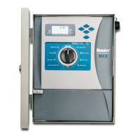
ICC2 has the Solar Sync soware built in to the controller,
and can be programmed on the control panel in a matter of
minutes. The controller will automatically increase or decrease
watering run times based on the sensor data learned from
changes in on-site weather. This results in a water-ecient
irrigation product that promotes water conservation and
healthier landscapes. For further programming instructions,
please refer to the Solar Sync Owner’s Manual or visit the
Solar Sync support section on our website at
www.hunterindustries.com/support/sensors/solar-sync.
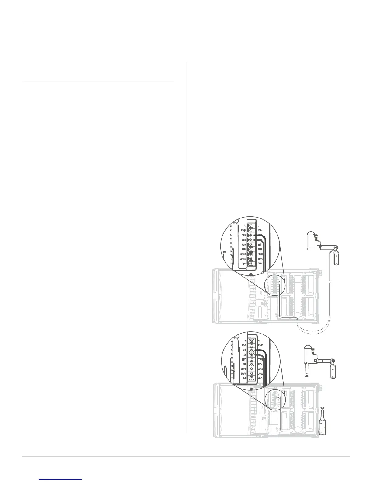
WIRED SOLAR SYNC INSTALLATION
1. Using the screws provided, mount the sensor in the
upright position on any surface where it will be exposed
to unobstructed sun and rainfall, but not in the path of
sprinkler spray. This can be a maximum 200' (60 m)
from the controller.
2. Route the green and black wire pair through any of the
available knockouts into the controller cabinet.
3. Remove the red jumper wire that is attached across the
two SEN terminals.
4. Connect either wire to one SEN terminal, and the second
wire to the other SEN terminal. It does not matter which
wire connects to which SEN terminal.
WIRELESS SOLAR SYNC INSTALLATION
1. Repeat steps 1–4 on the previous page; however, you will
connect the green and black wires from the Wireless Solar
Sync Receiver to the SEN terminals, as opposed to wires
coming from the sensor.
2. The receiver can be mounted in the knockouts provided
on the side of the controller, or to a wall with the wall
mounting bracket and hardware provided.
3. The sensor can be mounted up to 800' (240 m) from
the receiver. The receiver and sensor are pre-paired
with the same frequency. Once installed, the receiver
will automatically go into a “search” mode to look for a
signal from its paired sensor. However, it is a good idea to
manually initialize communication between the sensor and
receiver during installation to verify signal transmission.
4. Aer the receiver’s green and black wires have been
connected to the controller, the red LED in the center of
the receiver will turn on and stay solid for 10 seconds,
indicating that it is searching for a signal from the sensor.
5. While the receiver is searching, press and hold the spindle
on the sensor. The LED on the receiver will blink four
times and then turn o, indicating that the signal from the
sensor has been acknowledged.
6. To double-check or validate existing receiver/sensor
communication, press and hold the spindle on the sensor.
The LED on the receiver will blink twice, conrming that
the receiver is addressed to the sensor properly.
 Loading...