Built on Innovation
®
7
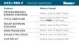
Components
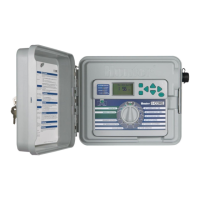
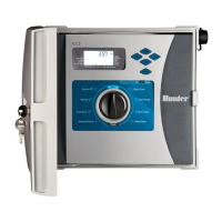
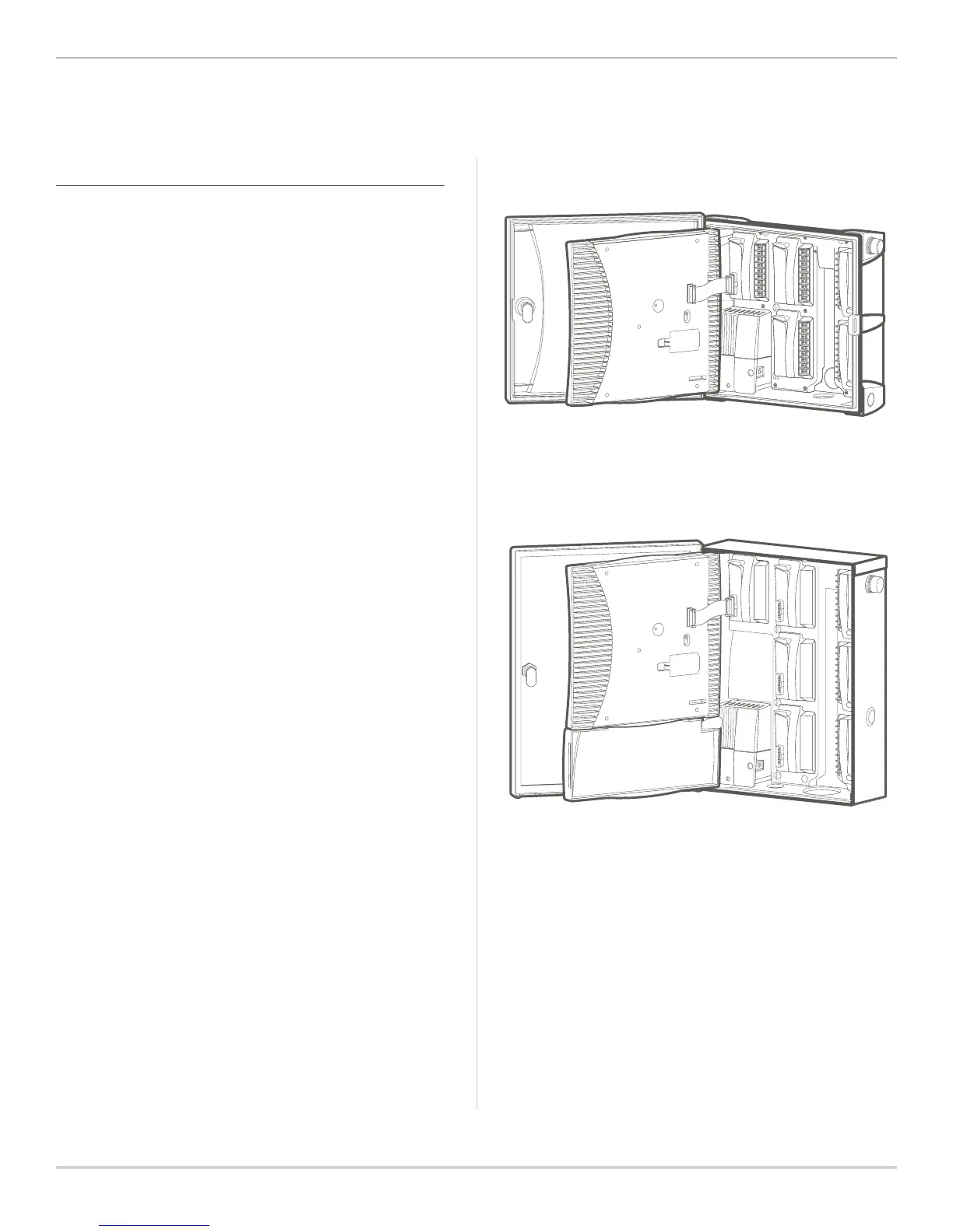
WIRING COMPARTMENT
1. Facepack/Control Panel: Primary console for
programming the controller.
2. Power Module: Provides power to the controller and must
be in place for controller to operate; contains 24 VAC,
sensor, remote, and P/MV terminals.
3. SmartPort Connector: Enables use of Hunter ROAM and
ROAM-XL remotes.
4. Transformer: Pre-installed with 120 VAC, 230 VAC, neutral,
and ground wires (includes additional earth grounding lug
for supplemental lighting protection).
5. Battery Compartment: Without AC power, a 9-volt battery
(not included) allows programming, while a 3-volt CR2032
lithium battery (included) keeps real-time clock.
6. Ribbon Cable: Connects facepack to power module, and
transmits information from the control panel to the inner
controller assembly.
7. Station Output Modules: Plug-in station modules used to
expand controller capacity in increments of 4, 8, and 22
stations (ICM-400, ICM-800, and ICM-2200).
8. Door Lock: Pre-installed lock assembly with 751 key
(alternative 701, 702, or 703 key/lock assemblies also
available).
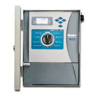
PLASTIC CABINET
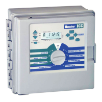
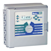
METAL CABINET
 Loading...