38 - English
2. SPECIAL MENU FUNCTIONS
Switches
Turn the main switch ON and OFF. ON should be
shown on the display when the switch is turned to the
ON position. When the switch is in the OFF position,
OFF should be shown.
Close the control panel cover to test the stop button.
When the cover is closed ON should be shown on the
display. Now press down the stop button and OFF
should be shown. On Solar Hybrid the stop button is
connected in series to the panel cover's switch.
Press Arrow back to exit the test.
Speaker
Place the cursor on Speaker and press YES. The
speaker should sound. If not, it is defective.
Press Arrow back to exit the test.
Loop (5-’2-4)
The test must be performed where there is a charging
station and boundary wire installed to get correct
values when testing the loop.
Place the cursor on Loop and press YES. Now read
the signal values.
• Af = The strength of the A-signal measured via
the front loop sensor on the mower. The value
should lie between approximately 70 and 320 to
ensure good functionality. The closer to the loop
the mower is, the higher the value. When the
Automower
®
is directly over the loop the value is
0 and when the mower is outside of the loop the
value is negative.
Ar = The strength of the A-signal measured via
the rear loop sensor on the mower. Ar is shown
when you press Arrow up. The guideline values
of approximately 70 – 320 also apply for Ar.
• G1 and G2 = The strength of the guide signal for
each guide wire measured via the front loop
sensor and close to the guide wire. To the left of
the guide wire, in the direction towards the
charging station, the value is negative and to the
right of the wire the value is positive. The guide
wire is named G1 for 220 AC and the guide wires
are named G1 and G2 for 230 ACX, Solar Hybrid
and 260 ACX. To ensure the functionality of the
guide wire, the value should be (-) 250 – 320 next
to the guide wire.
• F = an indication of the F-signal strength. The
F-signal is generated by the large coil in the
charging station plate.
• N = an indication of the N-signal strength. The
N-signal is generated by the two small coils in the
charging station plate.
• Quality = an indication of the loop’s overall
function. The normal value is 100 %. Another
value indicates there is a system malfunction.
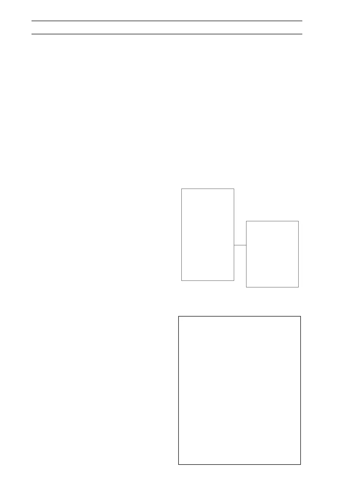
Power & Motors
User interface
Loop
Sensors
Af
G1
G2
Quality
Restarts
5-2-4
F
N
Loop system reminder:
The charging station generates four signals, one to
the boundary wire, one to the guide loop and two to
the coils in the plate.
A-signal: Signal that demarcates the working area.
Normal value for the A-signal: about 70 – 320.
Guide signal: Signal that delimits the guide area.
Default value for the Guide signal next to the guide
wire: about (-) 250 – 320.
F-signal: Remote signal that helps the Automower
®
to find the charging station. Normal value for F with
Automower
®
in the test position: Over 300.
N-signal: Near signal that guides the Automower
®
into the charging station. Normal value for N with
Automower
®
in the test position: Over 100.
The loop signals can only be interpreted if the
Quality value is 100 %. When the value is 99 % or
lower, the loop system does not function correctly
and with that, the displayed values for the signals
will not be correct.
 Loading...