44 - English
3. INSTALLATION
3. Installation
3.1 Charging station
The placement of the charging station should be well
planned in order to give the best installation and
function of the Husqvarna Automower
®
:
• The charging station should have a central
placement in the working area, so that the
Automower
®
can find it as soon as possible.
A central placement is of extra importance with
complex installations.
• Automower
®
finds the charging station much
easier when there is a large open area in front of
it. If you use a guide wire and follow it out from
the charging station, it is extremely important
with a large open space, likewise if you have set
the mower for a wide corridor (see 1.9 Corridor
width, page 16).
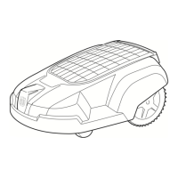
• The charging station must be positioned on
relatively level ground. The height difference
must not differ more than 5 cm (2”) between the
front and rear of the charging station.
• The battery is spared if charged in the lowest
possible ambient temperature. Consequently, it
is beneficial if the charging station can be placed
where it is shaded, especially during the warmest
parts of the day.
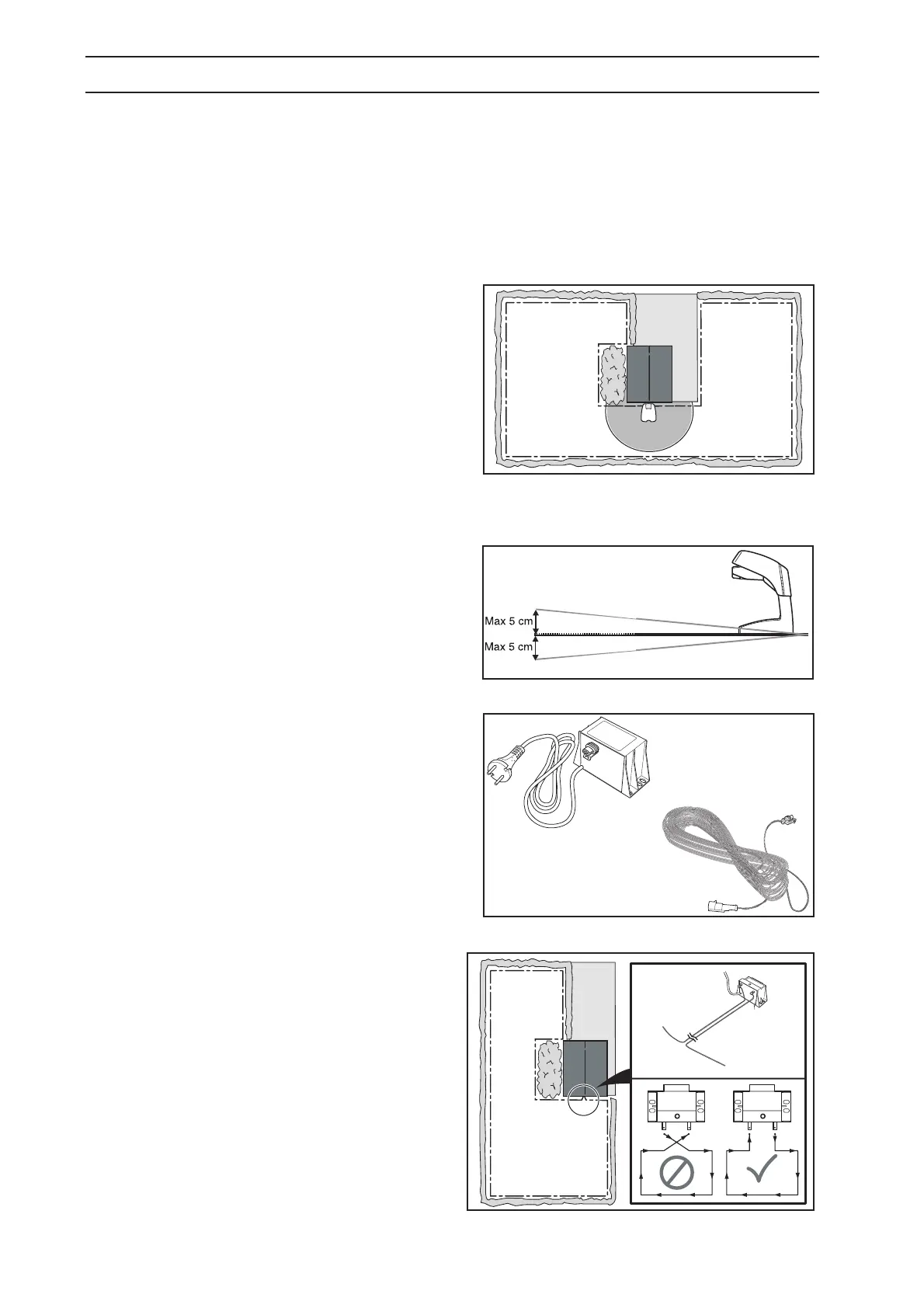
• The transformer must be placed where it is well
ventilated and is not exposed to direct sunlight.
Under no circumstances may it be enclosed in
any form of small box or plastic bag. The
transformer should be placed under a roof,
preferably indoors.
The supplied low voltage cable is 20 metres
(65 ft) long. The low voltage cable must not be
shortened nor extended.
It is recommended to use an earth fault-breaker
when connecting the transformer to the wall
socket.
Loop generator/charger (only 210C) should be
installed as the transformer above. The ends of
the boundary wire are run in parallel and close to
each other, in towards the loop
generator/charger.
• If you use a guide wire the charging station must
be placed so that the overall guide loop is not too
long. The guide loop should not be longer than
about 300 metres (1000 ft).
Guide loop = the guide wire from the charging
station to the T-connection on the boundary wire
+ the boundary wire from the T-connection (to
the left seen in the direction towards the charging
station) back to the charging station. For more
information about the guide loop, see 1.8.2
Guide loop, page 15.

 Loading...