English - 93
5. REPAIR INSTRUCTIONS
4. Remove the old card and replace with the new
card.
5. Screw the screws back in place and connect the
cable and the GSM module.
6. Program the mower with the latest control
program. A spare part box does not include a
mower program.
7. Check that the mower works.
8. Fit the chassis and body.
A new start-up sequence starts when the main switch
is turned to the ON position after replacing the control
box, provided that the data on the old control box has
not been transferred to the new via Autocheck first.
5.9 Replacing the display
1. Dismantle the body.
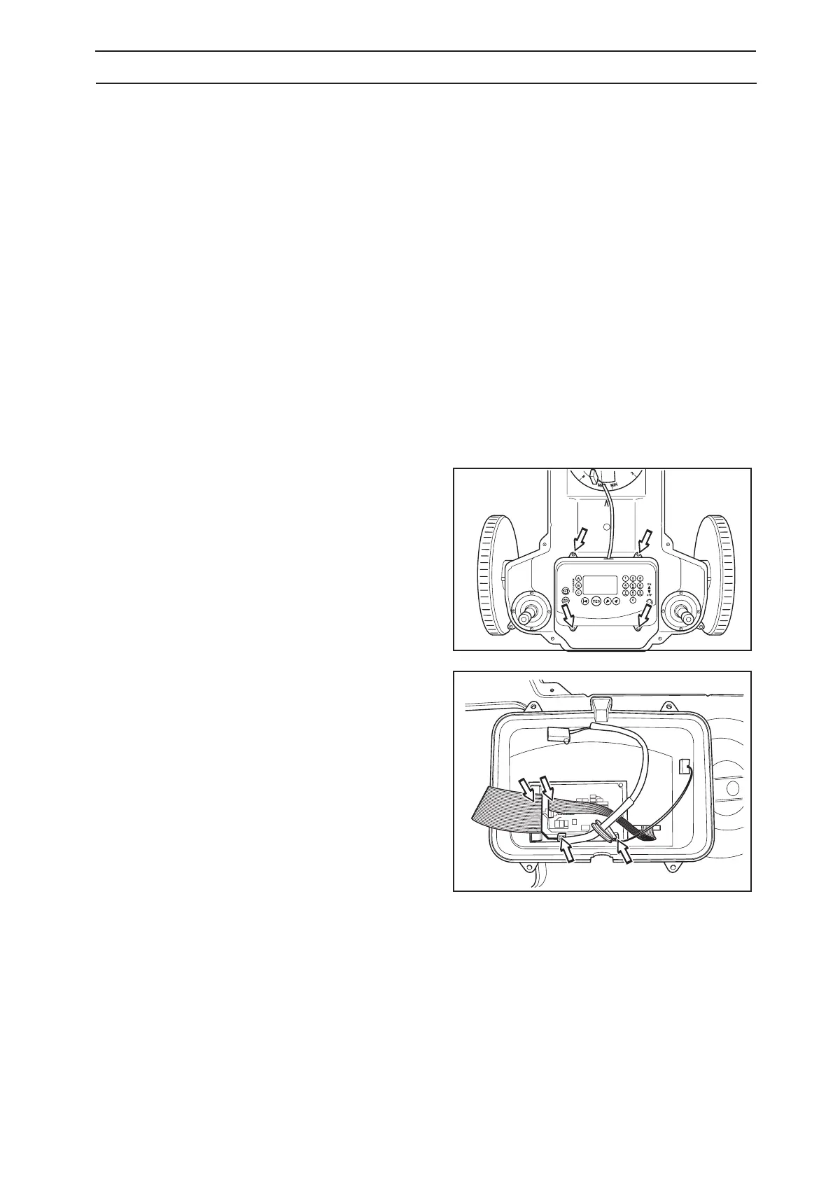
2. Unscrew the four screws, torx 20, holding the
display cover.
3. Disconnect all the cable connected to the display
circuit card; top part of the cabling, stop button,
main switch, keypad and background lighting
(not 210 C, 220 AC).
NOTE! Remove the cables by pulling respective
connectors.
4. Loosen the screw retainer and remove the
display.
5. Replace with a new display and reconnect all the
cables again. Ensure that the cable to the display
circuit card is connected the right way and that
the rubber grommet on the cable to the stop
button is fitted correctly. If the cable is connected
incorrectly, the buttons will not correspond with
the menu functions.
6. Test that the display and keypad work. The mower
program needs to be reconfigured for the new
display if the text on the display is inverted or dark.
This is done using the function Machine version in
Autocheck (see Tools page 29)
7. Replace any packing for the display cover with
new packing (m/2010). Screw on the display
cover.
8. Assemble the body.

 Loading...