3 Product and installation
3.1 Main components for installation
The robotic system involves 4 main components:
• Product
• Charging station
• Power supply
• Loop wire
Go to the manufacturer's website or read the Operator's
manual for further descriptions about the product and
the installation.
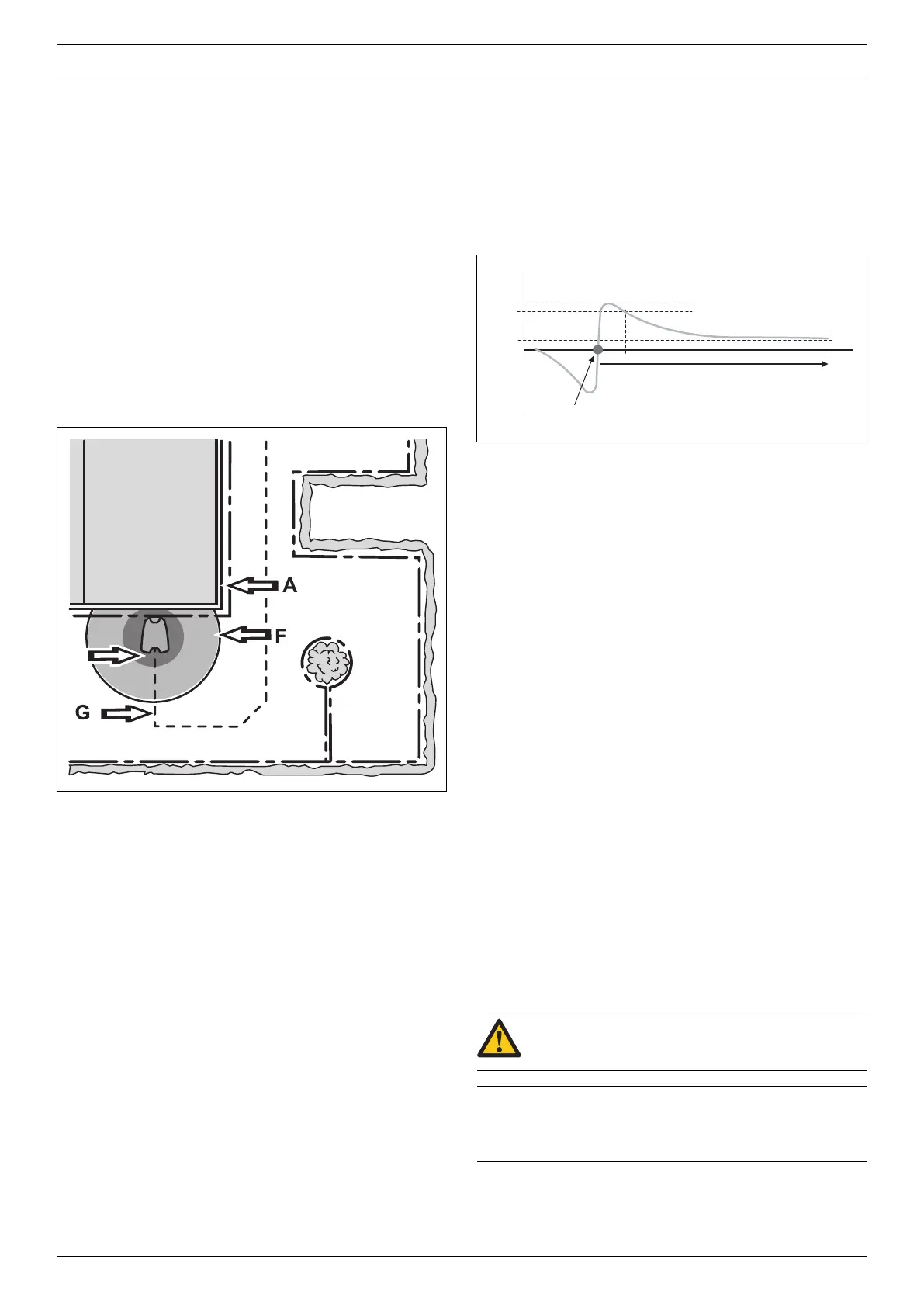
3.2 The loop system's control signals
The loop system includes the boundary wire and 1 or
more guide wires that are connected to the charging
station. The loop system transmits the signals that
follow:
• A signal, sets the boundary for the work area.
• F signal, is generated by a loop in the charging
station so that the product knows that it is near the
charging station.
• N signal, is generated by a loop in the charging
station baseplate to guide the product correctly into
the charging station.
• Guide signal, G, guides the product to the charging
station, but can also be used to guide the product
from the charging station to a remote area.
To do a check of the A, F, N and Guide signals, refer to
the
Loop signal on page 56
.
3.3 LED indicator lamp on the charging station
The loop system’s status is easily checked using the
LED indicator lamp on the charging station. Refer to
Loop signal on page 56
.
3.4 Boundary loop
The strength of the A signal varies depending on the
distance. The strength of the signal is high close to the
wire. The strength subsequently diminishes the farther
away from the wire you get. Outside the work area the
signal is negative and its strength diminishes more
rapidly. Signal quality should always be 100% for
satisfactory function.
The strength of the signal is affected by the size of the
work area, islands, headlands, passages and corners.
The signal can also be affected by magnetic objects in
the ground or in nearby walls and buildings. Examples of
magnetic objects are iron fences, iron girders and
reinforcement bars. Grass areas laid on concrete roofs
can therefore lead to a weaker signal.
The A signal’s reception and amplification can vary by
+/- 10% from one product to another. This means that at
the same point in an installation, one product can
display A=90 and another one A=100. The charging
station’s circuit board and the product’s loop sensor can
also give certain variations between different products.
3.4.1 To test the boundary loop
The product displays the
No loop signal
message if an
attempt is made to start the product before the
installation is complete.
However, it is possible to test the product before the
installation is completed by doing one of the following:
• Connect a short, temporary loop around the product.
• Temporarily deactivate the product’s loop detection.
Refer to
Tools - Special settings on page 13
.
3.4.2 Obstacles
To demarcate an obstacle, you can put the boundary
wire from the edge of the work area to the obstacle,
around it and then back.
CAUTION: The boundary wire must not be
crossed on its way to and from an island.
Note: If the obstacle is relatively large compared to the
work area, it can have an impact on the product inside
the entire work area.
6 - Product and installation 1191 - 001 -

 Loading...