INSTALLATION
HPR400XD Manual Gas Instruction Manual 3-43
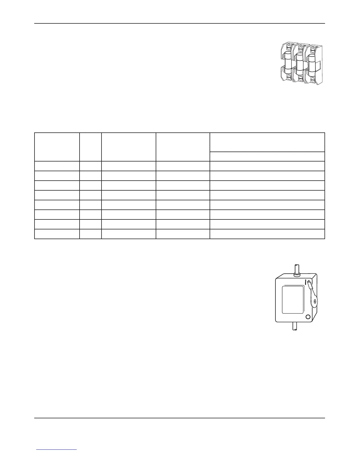
Line disconnect switch
The line disconnect switch serves as the supply-voltage disconnecting (isolating) device. Install
this switch near the power supply for easy access by the operator.
Installation must be performed by a licensed electrician and according to applicable national
and local codes.
The switch should:
• Isolate the electrical equipment and disconnect all live conductors from the supply
voltage when in the “OFF” position
• Have one “OFF” and one “ON” position clearly marked with “O” (OFF) and “l” (ON)
• Have an external operating handle capable of being locked in the “OFF” position
• Contain a power-operated mechanism that serves as an emergency stop
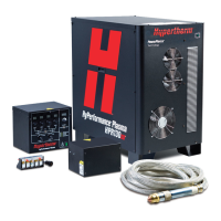
• Have slow-blow fuses installed for the proper breaking capacity (see table above).
Power requirements
General
All switches, slow-blow fuses and power cables are customer-supplied and must be chosen as
outlined by applicable national and local electrical codes. Installation must be performed by a
licensed electrician. Use a separate, primary, line disconnect switch for the power supply.
Note: The main feed protection device (Circuit Breaker or Fuse) must be sized to handle all branch-feed loads
for both inrush and steady-state current. The power supply must be wired into one of the branch-feed
circuits. The power supply has a steady-state current listed in the table below and has an inrush current of
10 times the rated input current, which can last up to 0.20 seconds or 10 line cycles.
Power cable
Wire sizes vary based on the distance of the receptacle from the main box. The wire sizes listed in the table above were
taken from the National Electric Code 1990 handbook, table 310.16 (USA). Use a 4-conductor Type SO input power
cable with a conductor temperature rating of 90° C (194° F). Installation must be performed by a licensed electrician.

 Loading...