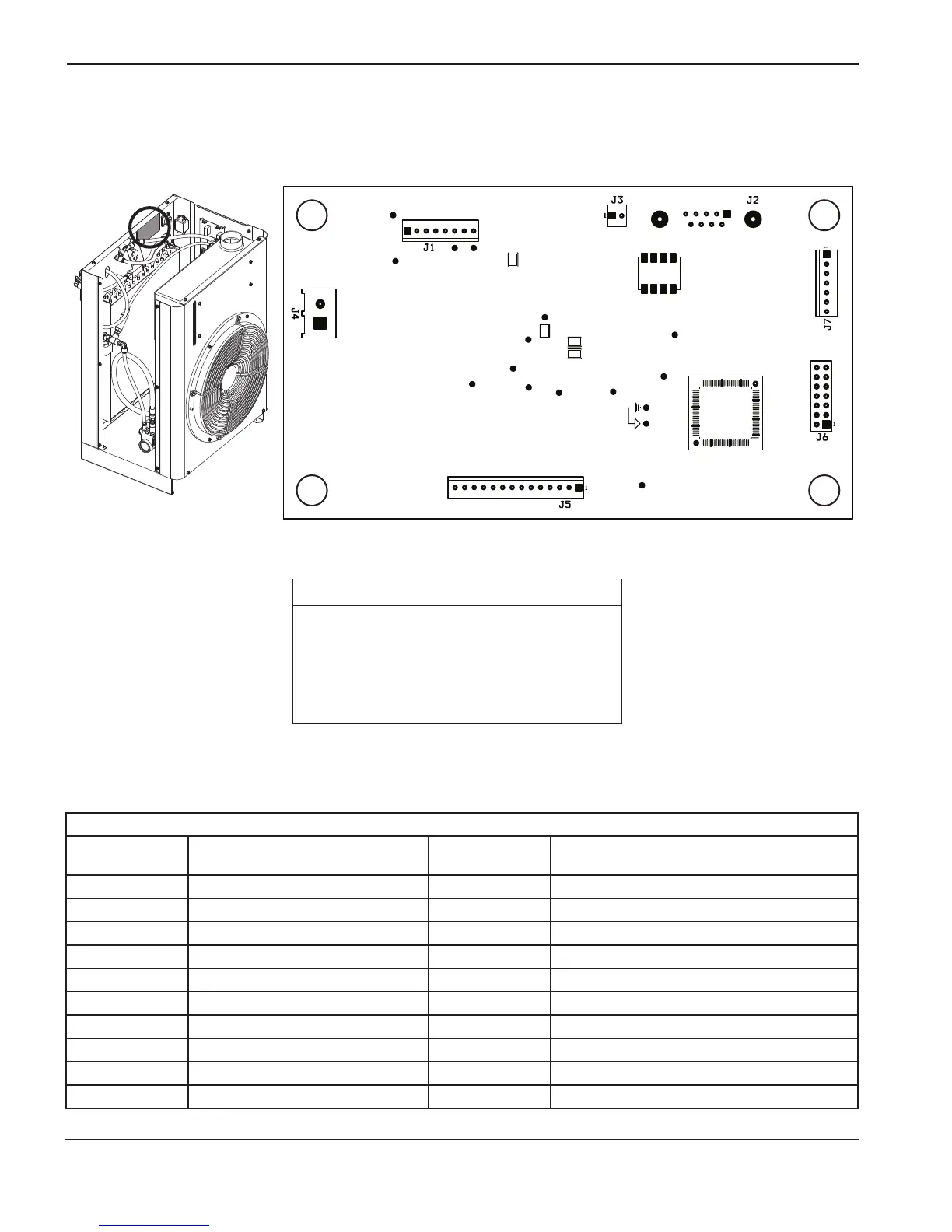
Control PCB test points
Test point
number
Description
Test point
number
Description
TP1 A + 3.3 V TP12 Digital ground
TP2 Analog ground TP13 + 3.3 V
TP3 Pressure sensor (for use in the future) TP14 SCIRXD (RS422 transmit)
TP4 + 5 V TP15 Digital ground
TP6 + 3.3 V TP16 Analog ground
TP7 + 24 V TP17 Reset\
TP8 Power ground TP18 Reset
TP9 Coolant flow sensor input TP21 + 15 V
TP10 Chiller flow input (for use in the future) TP22 – 15 V
TP11 SCIRXD (RS422 receive) TP23 Line voltage input
LED Signal name Color
D1 + 5 VDC Red
D2 + 3.3 VDC Green
D7 CAN TX
D8 CAN RX

 Loading...