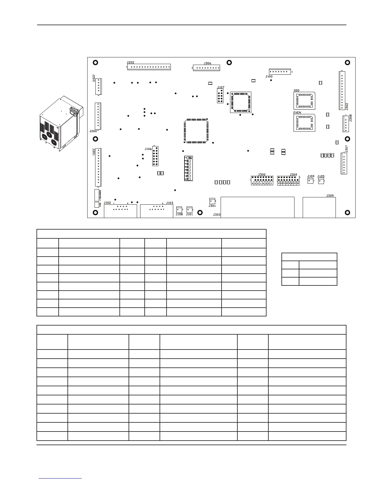
Control PCB test points
Test point
number Description
Test point
number Description
Test point
number Description
TP105 WDI TP117 CAN ground TP206 Chopper 4 analog input
TP108 Reset TP118 CCA+ TP207 Chopper control D
TP109 Reset TP119 CCC+ TP208 DAC output A
TP110 Digital ground TP120 CRXD (CANL) TP209 DAC output B
TP111 Analog ground TP200 Chopper 1 analog input TP210 Chopper A temperature sensor
TP112 A + 3.3 V TP201 Chopper control A TP211 Chopper B temperature sensor
TP113 + 3.3 V TP202 Chopper 2 analog input TP212 Chopper C temperature sensor
TP114 + 5 V TP203 Chopper control B TP213 Chopper D temperature sensor
TP115 CANH TP204 Chopper 3 analog input TP214 Work lead analog input
TP116 CANL TP205 Chopper control C
Firmware
Item Part number
U110 081135 EVEN
U109 081135 ODD
Control PCB LED list
LED Description Status LED Description Status
D107 + 5 V OK Steady D312 Hold
D108 + 3.3 V OK Steady D313 Pierce
D110 CAN transmit LED Blinking D314 Corner
D111 CAN receive LED Blinking D315 Start redundant
D308 Motion D316 Pilot arc enable
D309 Error D317 Spare
D310 Ramp-down error D324 Phase loss
D311 Not ready D329 Pump motor-drive OK Steady when OK

 Loading...