Note
The IBC boiler (like any modern appliance that contains electronic equipment) must have a
“clean” power supply, and is susceptible to power surges and spikes, lightning strikes and
other forms of severe electrical “noise”. Power conditioning equipment (surge protectors,
APC or UPS devices) may be required in areas where power quality is suspect.
3.10.2 120VAC line-voltage hook-up
Line-voltage wiring is done within the field-wiring box (see Wiring diagrams on page 93). Connect the
boiler to the grid power using a separate, fused circuit and on/off switch within sight of the boiler. Use 14-
gauge wire in BX cable or conduit properly anchored to the boiler case for mains supply and pump
circuits.
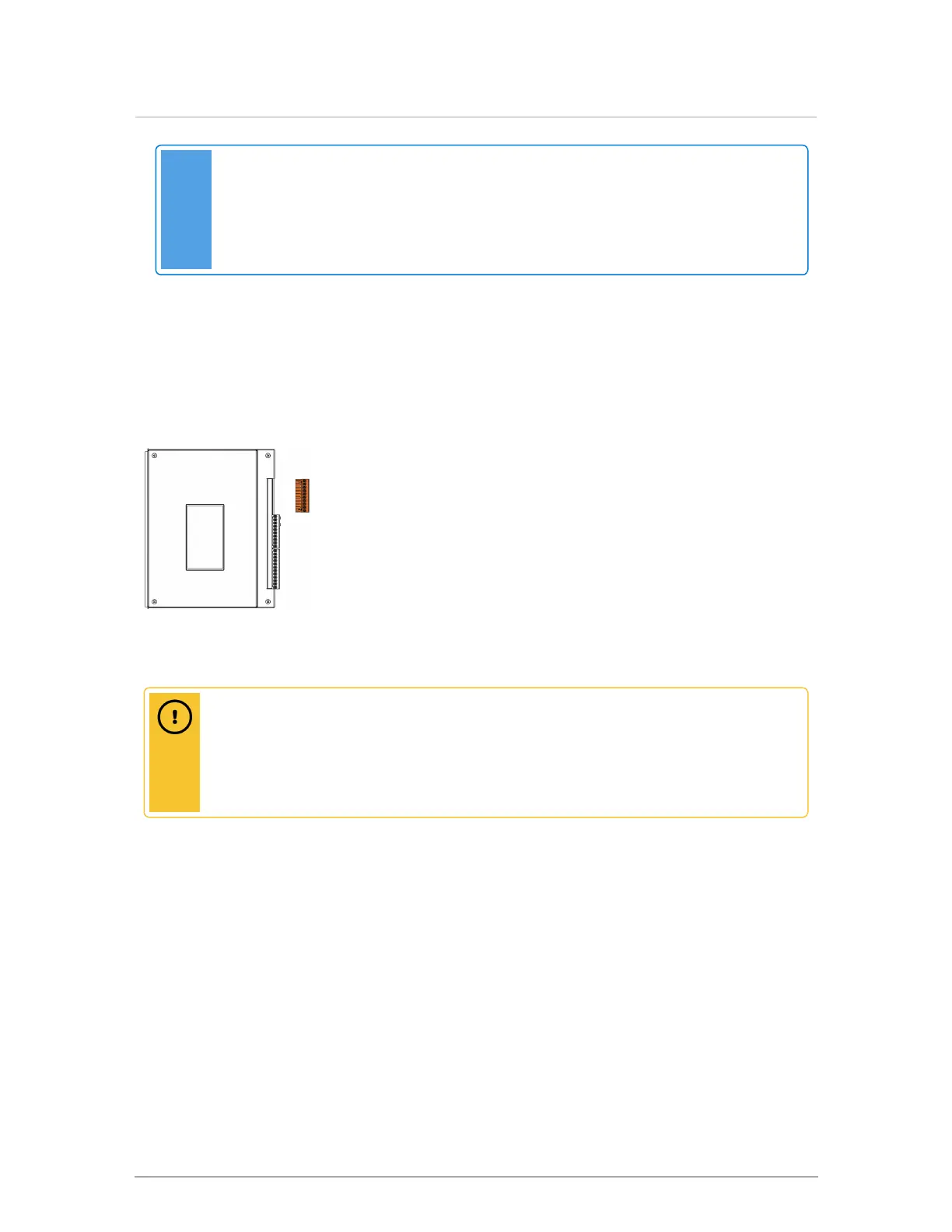
Figure 33 Line voltage load pump terminals
Caution
The on-board controller load pump relays are protected with 5 Amp fuses. The maximum
recommended load on each fuse is 4 Amps (80% of rating). The maximum combined pump
load is 10 Amps. Isolation relays or contactors must be used if the loads exceed these
maximums.
Connect a 120VAC / 15 amp supply to the “AC IN” tagged leads in the wiring box.
3.10.2.1 Load pumps
The 120VAC power supply to the load pumps (P/V1, P/V2, P/V3, and P/V4) is factory installed and
connected to P/V-L and P/V-N for your convenience. If you use the P/V relay connections for zone valves,
you need to remove and cap off the 120VAC connections at P/V-L and P/V-N. The 24VAC can then be
applied using an external transformer to supply power to zone valves. The upper 4 pairs of contacts on
the connector strip are then powered to manage up to 4 load pumps – the top pair for Load 1, the second
pair for #2 etc. Once the controller is programmed for the respective loads, the boiler manages all the
loads without need of further relays (for loads up to ⅓ HP; for more – use a protective relay).
 Loading...