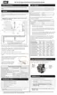
Fan
Mixing device
High pressure switch
Inlet gas pressure test port (location of)
Low pressure switch
Low fire adjustment (zero-offset)
High fire adjustment (on the side)
Manifold gas pressure test port
Shutoff valve
Figure 37 EX 700, 850 - gas valve and fan components
6.3.1 Replacing the fan
1. Turn off the electric power and gas supply to the boiler.
2. Ensure the boiler cools down to the surrounding temperature. Do not drain the boiler unless
freezing conditions are expected during this procedure.
3. Remove the front cover, and then remove the boiler's top panel by removing the Torx screws on the
top panel of the boiler.
A ladder or step may be required to have a clear vertical view of the work area. Do not attempt to
reach from the front without a clear view, as damage to connectors, screws or refractory may occur.
4. Unplug both the upper and lower electrical connectors from the fan.
5. Position the harnesses out of the way of the heat exchanger lid.
6.
Remove the four 5/16" hex head bolts that attach the gas valve to the mixing device. (See on
Figure 38 .) These bolts should be first loosened slightly in a cross sequence to prevent deformation
of the mating parts.
7. Carefully move aside the gas valve assembly, and retain the O-ring for re-installing.
8. Remove the four (4) ¼" hex bolts that connect the mixing device to the air filter box. The gasket
should remain attached to the air filter box.
 Loading...