9. Remove the four (4) hex bolts that attach the fan to the heat exchanger lid. An open-ended
wrench or socket is required.
10. With the mixing device still attached, remove the fan by pulling straight up ensuring that no wires
are caught and that the gas line remains in place. Place the removed components in a clean,
dry area.
11. Note how the mixing device is positioned on the fan before removing it from the fan. Remove the
six (6) 6 mm screws to separate the mixing device from the fan.
12. Attach the mixing device to the new fan.
13. Re-install the components in reverse order of the steps above.
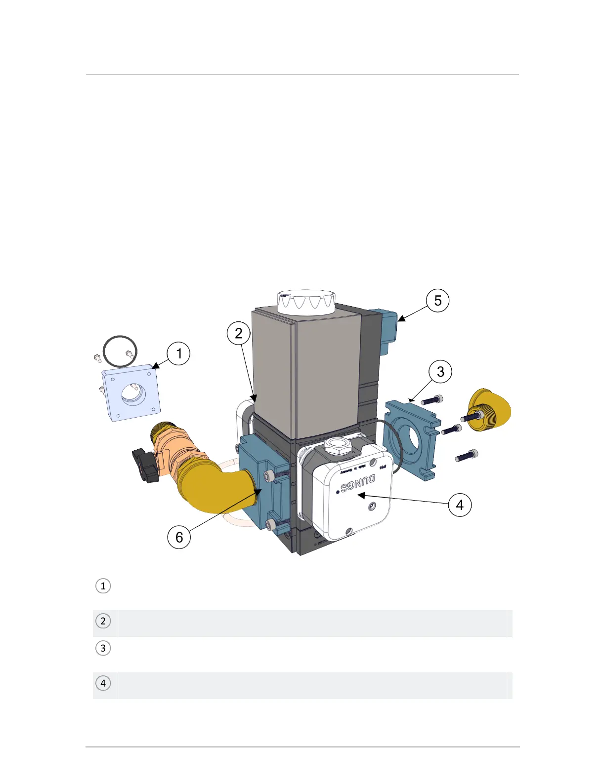
6.3.2 Replacing the gas valve
Unscrew four (4) bolts to separate the gas valve from the mixing device. Keep gasket and bolts
for re-assembly.
Location of high gas pressure switch.
Gas valve inlet: Unscrew the four (4) bolts of the flange to separate gas valve from the gas
valve. Keep gasket and bolts for re-assembly.
Low gas pressure switch.
Section: Service and maintenance
 Loading...