EasyManuals Logo
Home>IBM>Desktop>5150

IBM 5150 Hardware Maintenance Manual

IBM 5150
357 pages
To Next Page IconTo Next Page
To Previous Page IconTo Previous Page
Page #218 background imageLoading...
Page #218 background image
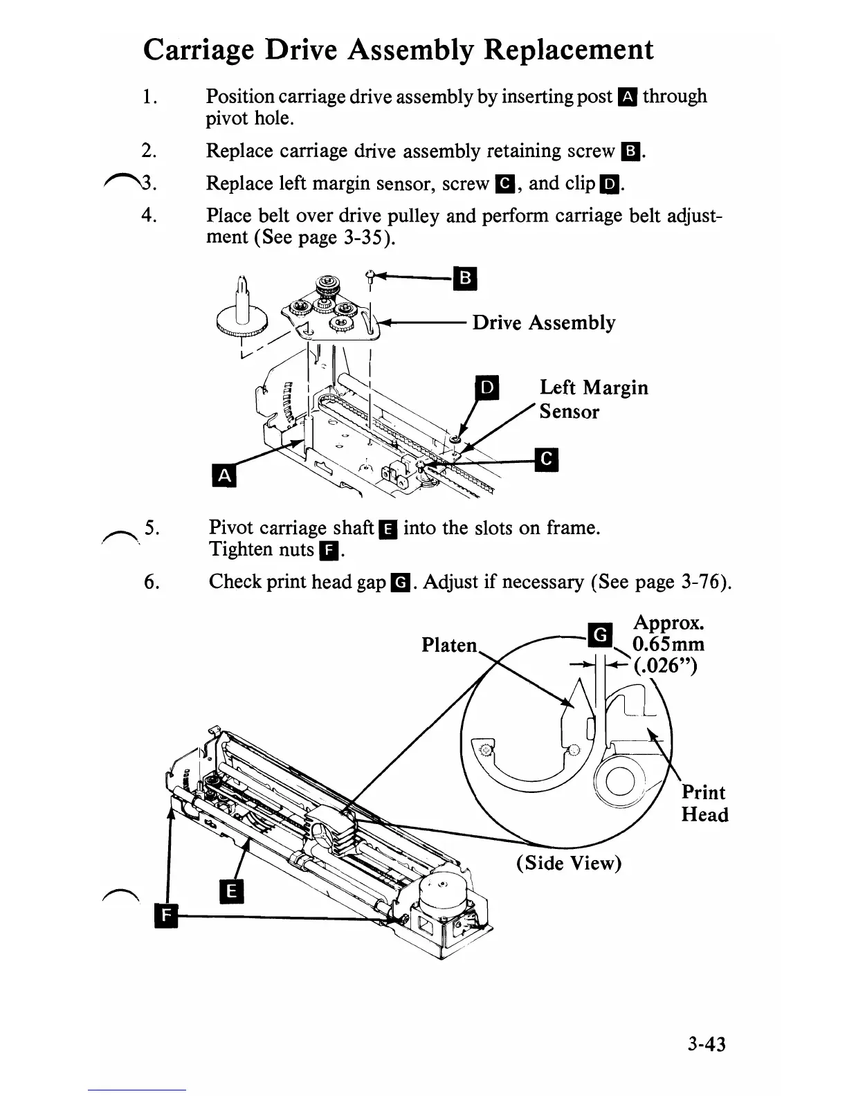
Carriage Drive Assembly Replacement
1.
Position carriage drive assembly by inserting post
II
through
pivot hole.
2.
Replace carriage drive assembly retaining screw
Ii).
~.
Replace left margin sensor, screw
II,
and clip
m.
4. Place belt over drive pulley and perform carriage belt adjust-
ment (See page 3-35).
""---1iJ
Left
Margin
Sensor
,~,5.
Pivot carriage shaft
II
into the slots on frame.
Tighten nuts
g.
6.
Check print head gap
m.
Adjust
if
necessary (See page 3-76).
r.I
Approx.
l1li
O.65mm
~
'(.026")
Print
Head
3-43

Table of Contents

Other manuals for IBM 5150

Questions and Answers:

Question and Answer IconNeed help?

Do you have a question about the IBM 5150 and is the answer not in the manual?

IBM 5150 Specifications

General IconGeneral
BrandIBM
Model5150
CategoryDesktop
LanguageEnglish

Related product manuals