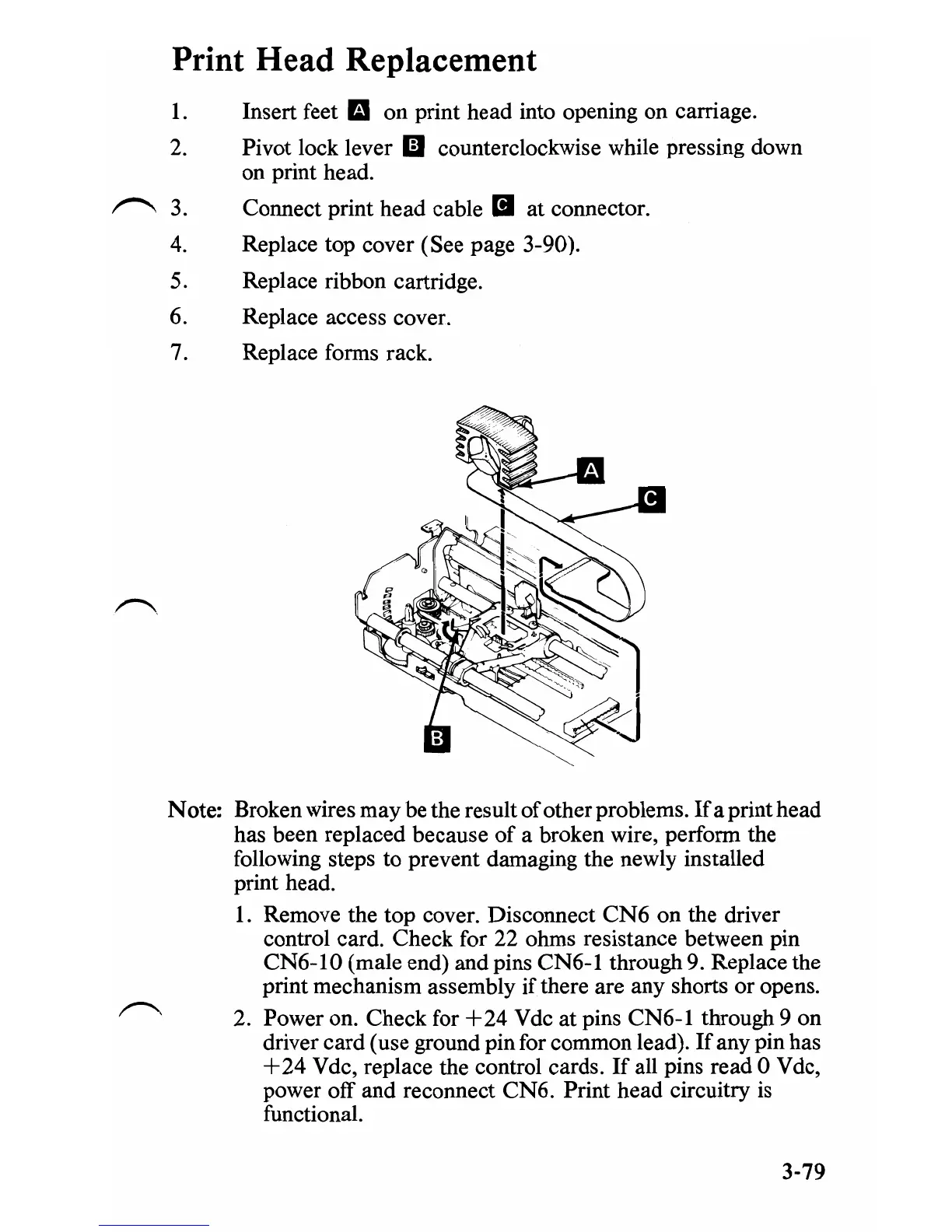
Print Head Replacement
1.
2.
~3.
4.
5.
6.
7.
Insert feet lit on print head into opening on carriage.
Pivot lock lever
II
counterclockwise while pressing down
on print head.
Connect print head cable
II
at connector.
Replace top cover (See page 3-90).
Replace ribbon cartridge.
Replace access cover.
Replace forms rack.
Note: Broken wires may be the result
of
other problems.
If
a print head
has been replaced because
of
a broken wire, perform the
following steps
to
prevent damaging the newly installed
print head.
1. Remove the top cover. Disconnect
CN6
on
the driver
control card. Check for 22 ohms resistance between pin
CN6-10
(male end) and pins CN6-1 through 9. Replace the
print mechanism assembly
if
there are any shorts
or
opens.
2. Power on. Check for
+24
Vdc at pins CN6-1 through 9 on
driver card (use ground pin for common lead).
If
any pin has
+24
Vdc, replace the control cards.
If
all pins read 0 Vdc,
power off and reconnect
CN6.
Print head circuitry is
functional.
3-79
 Loading...