DANGER
To prevent power from switching on automatically during service procedures, select manual or secure mode
on the system unit control panel or disconnect the cables that connect to J15 and J16 on the frame being
serviced. (RSFTD211)
This page includes the following:
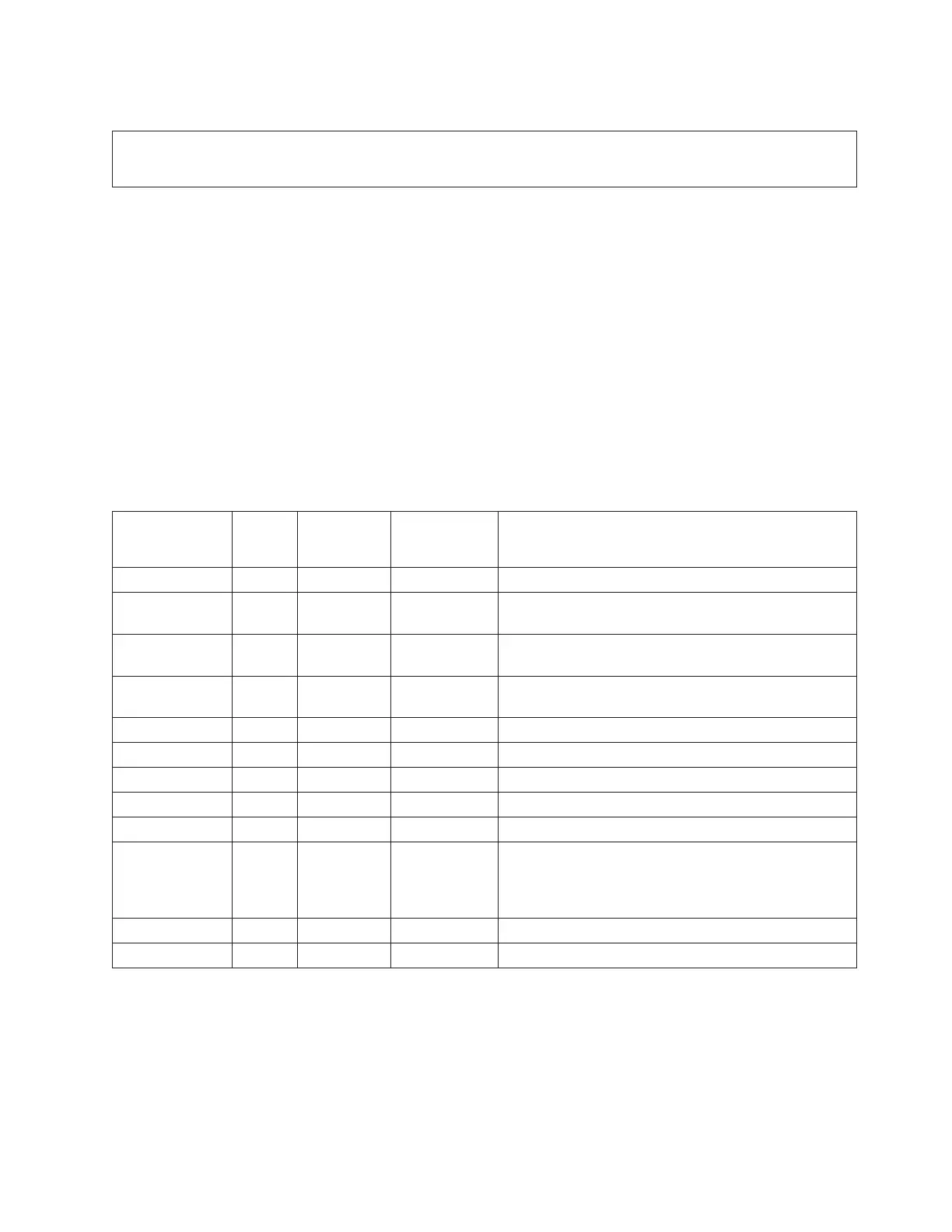
v “Breaking down the SRC”: defines the fields of the SRC and their corresponding Control Panel function.
v “DSA breakdown”: helps you determine a part position and item from the Direct Select Address (DSA).
v “Card positions” on page 65: contains the card positions for the model you are working on.
v “Converting from HSL loop number to port labels on the system unit or processor tower” on page 72
Breaking
down the SRC: This table defines the fields of the SRC and their corresponding Control Panel
function. Word 7 of the SRC allows you to determine the correct Bus number, bus type, multi-adapter
bridge number, multi-adapter bridge function number and logical card number from the Direct Select
Address (DSA). Physical card slot labels and card positions for PCI busses are determined by using the
DSA and the appropriate system unit or expansion tower card position table. See “Card positions” on page
65 in this page.
Table 1. SRC breakdown
SRC word
Control
panel
function
Panel
function
characters Format Description
1 11 1-8 B600 uuuu uuuu = unit reference code (69xx)
1-extended SRC
information
11 9-16 iiii Frame ID of the failing resource
1-extended SRC
information
11 17-24 ffff Frame location
1-extended SRC
information
11 25-32 bbbb Board position
2 12 1-8 MIGVEP62 See Hardware SRC formats for details.
3 12 9-16 cccc cccc Component reference code
4 12 17-24 pppp pppp Programming reference code
5 12 25-32 qqqq qqqq Program reference code high order qualifier
6 13 1-8 qqqq qqqq Program reference code low order qualifier
7 13 9-16 BBBB Ccbb Bus, card, board Direct Select Addresses (DSA). See
“DSA breakdown” below. If BBBB is greater than or
equal to 0100, then the BBBB value is the HSL loop
number.
8 13 17-24 TTTT MMMM Type and model of failing item (if non-zero)
9 13 25-32 uuuu uuuu Unit address (if non-zero)
DSA breakdown: Follow the instructions below to determine a part position and item from the Direct
Select Address (DSA).
1. Break down the DSA into the bus number, the multi-adapter bridge number, and the multi-adapter
bridge function number as shown in the Table 2. DSA breakdown (See page 64) below.
2. Use the System Configuration List or Hardware Service Manager (HSM) to determine if the bus is
located in the system unit or an I/O tower.
Analyze hardware problems 63
 Loading...


