Procedure
1. Ensure that you have the electrostatic discharge (ESD) wrist strap on and that the ESD clip is plugged
into a ground jack or connected to an unpainted metal surface. If not, do so now.
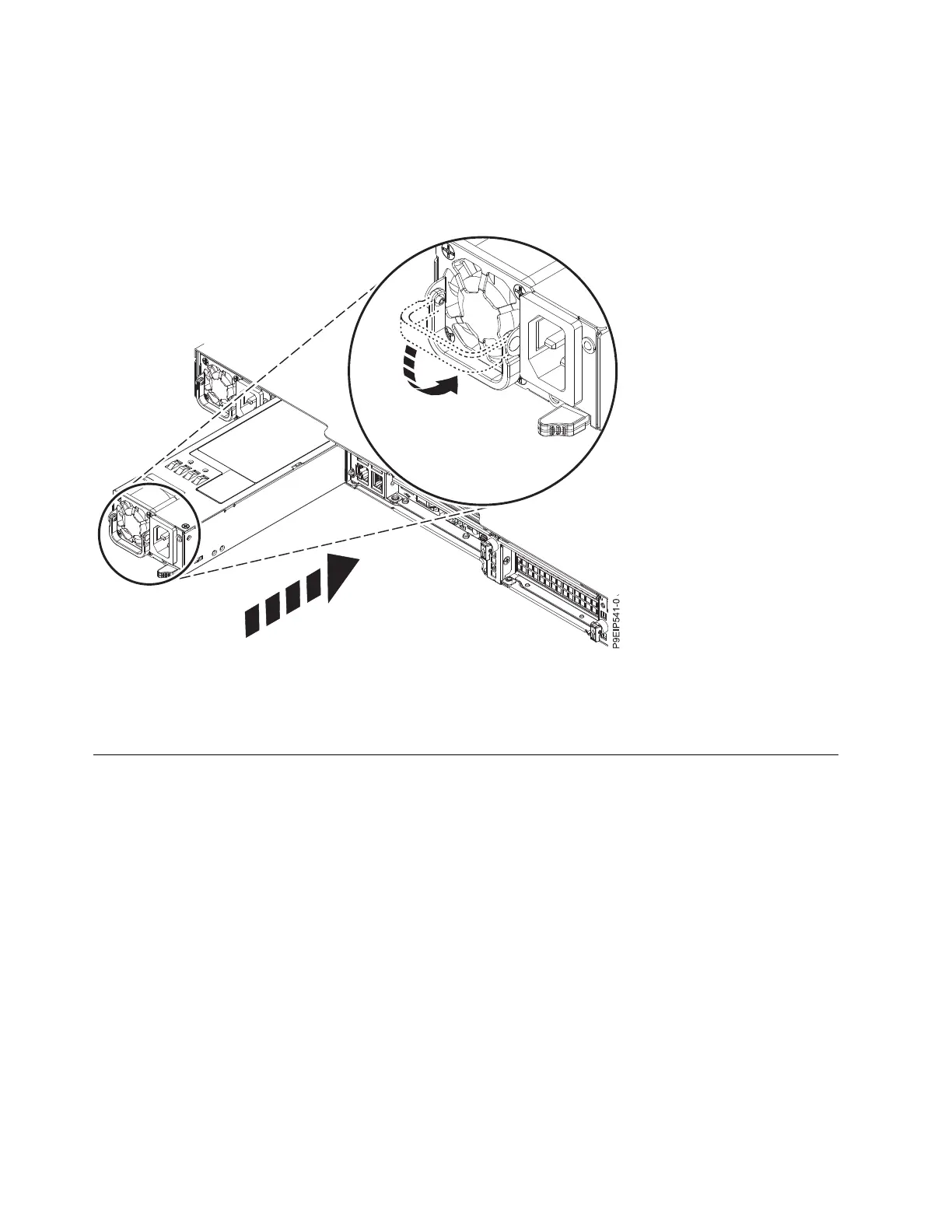
2. Align the power supply with the bay as shown in Figure 27. The fan is on the left; the plug is on the
right. Slide the power supply into the system until the latch locks in place.
3. Reconnect the power cord. For instructions, see “Connecting the power cords to a 7063-CR1 system”
on page 80.
Removing and replacing the system backplane in the 7063-CR1
Learn how to remove and replace the system backplane in the IBM 7063-CR1 Hardware Management
Console system.
Before you begin
Before you begin replacing the system backplane, write down the system serial number and machine
model type. After you replace the system backplane, you must set the system serial number and machine
model type in the system backplane.
About this task
Attention: The following procedures describe the removal and replacement of the system backplane.
Only an authorized service representative must remove or replace this part.
You can use a commercially available magnetic tip screwdriver to remove and replace the screws.
Figure 27. Replacing a power supply in the system
28 Power Systems: Servicing the 7063-CR1 Hardware Management Console system
 Loading...