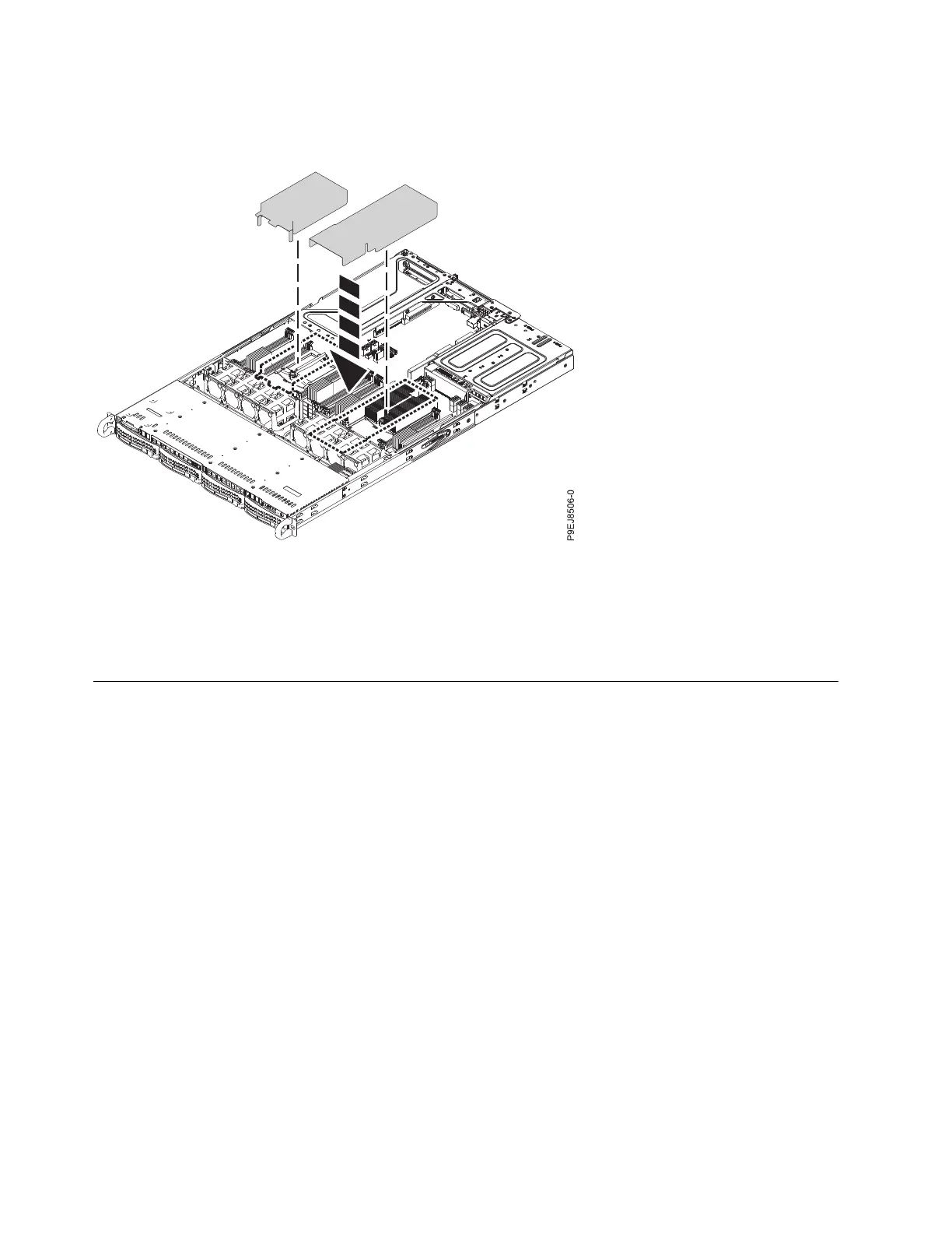
5. Install the system processor air baffle as shown in Figure 17. Insert the edge of the system processor
air baffle into the fan support. Then, carefully press the system processor air baffle down into place.
What to do next
Prepare the system for operation. For instructions, see “Preparing the 7063-CR1 system for operation after
you remove and replace internal parts” on page 68.
Removing and replacing memory in the 7063-CR1
Learn how to remove and replace memory in the IBM 7063-CR1 Hardware Management Console system.
Before you begin
Power off the system and place it in the service position. For instructions, see “Preparing the 7063-CR1
system to remove and replace internal parts” on page 66.
About this task
The memory must be four 8 GB memory modules of the same type. Four memory modules plug into the
following positions:
v P1M1-DIMMA and P1M1-DIMMB
v P1M2-DIMMA and P1M2-DIMMB
Procedure
1. Attach the electrostatic discharge (ESD) wrist strap. The ESD wrist strap must be connected to an
unpainted metal surface until the service procedure is completed, and if applicable, until the service
access cover is replaced.
Figure 17. Installing the system processor air baffle
20 Power Systems: Servicing the 7063-CR1 Hardware Management Console system
 Loading...