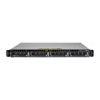
Preparing the 7063-CR1 system to remove the system backplane
Learn how to prepare to remove the system backplane from the IBM 7063-CR1 Hardware Management
Console system.
Before you begin
Before you begin replacing the system backplane, write down the system serial number and machine
model type. After you replace the system backplane, you must set the system serial number and machine
model type in the system backplane.
Procedure
1. If possible, have the customer create a backup of the BMC by completing the following steps:
a. Access the BMC GUI from a browser. The user needs Administrator privilege. You can use either
Google Chrome or Mozilla Firefox browsers.
b. Navigate to Maintenance > IPMI Configuration.
c. Press the Save button to create the backup. The file is named save_config.bin
2. If possible, have the customer save the BMC network settings by completing the following steps:
a. Navigate to HMC Management > Console Settings > Change BMC/IPMI Network Settings
b. Record the following values:
IP address
Subnet mask
Gateway
3. Power off the system and place it in the service position. For instructions, see “Preparing the
7063-CR1 system to remove and replace internal parts” on page 66.
Removing the system backplane from the 7063-CR1
Learn how to remove the system backplane from the IBM 7063-CR1 Hardware Management Console
system.
About this task
You can use a commercially available magnetic tip screwdriver to remove and replace the screws.
As part of the system backplane replacement, the system processor modules are moved from the old
system backplane to the new system backplane.
As part of the system processor module replacement, the heat sink is removed. When the heat sink is
removed from the system processor module, the thermal interface material (TIM) is typically adhered to
the heat sink. Unless damaged, the TIM that is adhered to the heat sink can be reused. If the TIM is
damaged, do not reuse the removed heat sink. Before you begin the processor removal and replacement
procedure, ensure that you have a spare TIM and heat sink on hand.
Procedure
1. Attach the electrostatic discharge (ESD) wrist strap. The ESD wrist strap must be connected to an
unpainted metal surface until the service procedure is completed, and if applicable, until the service
access cover is replaced.
Removing and replacing parts in the 7063-CR1 29
 Loading...